Poor auto timebase selection and ref-out modulation on the HP-53131A | |
|
I've recently run into two external reference clock input/output troubles with my Hewlett-Packard HP-53131A frequency counter:
This leads to some (somewhat) serious investigation of what's going on in the oscillator and PLL blocks of the schematic. To keep track of my notes I surgically opened the HP 'CLIP' PDF file (CLIP stands for Component Level Information Package), extracted the meaningful bits and gathered that in a glorious SVG. I could then work in vector graphics, adding scope screenshots and notes:  Watch your eyes kids: what debugging looks like in hardware. Click to see the full SVG. First thing to check was the timebase circuit itself. The HP-53131A (and its HP53132A/HP53181A siblings) have a standard 10MHz oscillator, whose signal is ignored completely if a better oscillator is in the device (options 001, 010 and 012). My counter has option 001 and I could see that Q16 was correctly switching the output of U33-C depending on whether I connected the opt-001 oscillator or not. U31-A, used to derive the HP-IB clock, was also looking good. However, the "LCLKOFF" signal fed into U33-A was problematic: it would disable the internal oscillators even when no external oscillator was present. WTF? This is the timebase selection issue I was experiencing: if an external reference is fed into the counter, then the counter uses it as expected. But if no external timebase is present, LCLKOFF still disables the local oscillators (options or standard). But then... how on earth is the counter still working with no timebase? Time to analyze the PLL block. The top part (U1 and U2) is where the CPU selects the timebase or its frequency (internal, external 10MHz, external 5MHz or external 1MHz). Using those frequencies as external input references showed that the CPU could detect the various timebase frequencies and lock on them normally. No issue there. That left U3 as the potential culprit. But since it was locking properly when a signal was applied, surely it could be dead? An interesting point was that the PLL would lock on a 5MHz signal when no external timebase was fed in, but that signal seemed to come from nowhere. The scope did confirm a noisy input on pin 14 of U3 (PLL input): 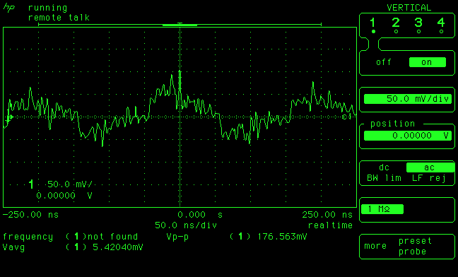 U3-14 at 50ns/div. The 5MHz parasite is clearly visible and significant (> 150mVpp) Pro tip: check out my python script to extract awesome CRT bitmaps through HPIB! Given the noisy signal the PLL struggles to lock on it and the entire reference becomes unusable: my 3325B will for example not lock on the ref-out signal from the counter. This struggle appears clearly on pins 1 (lock detect), 2 (comparator 1) and 13 (comparator 2) of the PLL circuit: 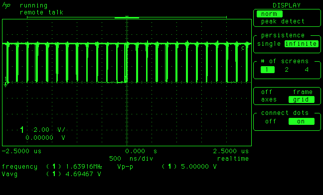 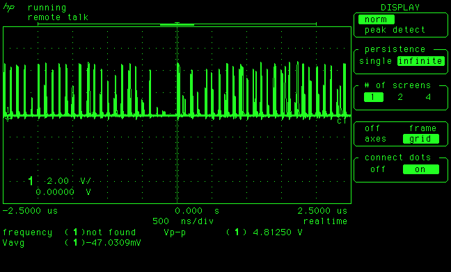 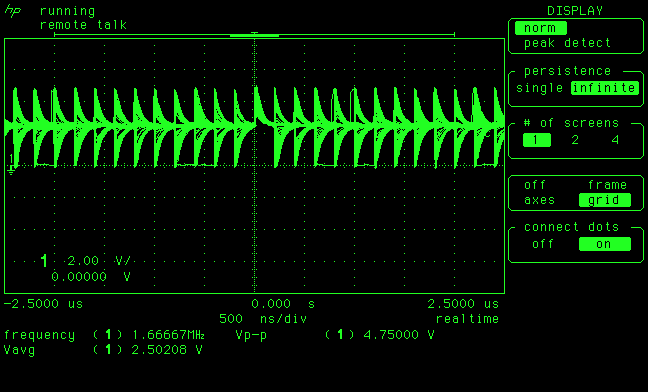 Pins 1, 2 and 13 of PLL circuit U3 when the noisy parasitic 5MHz reference signal is picked up by the timebase input circuit. An interesting test was to put a 50 ohm terminator on the external reference input. This reduced the input noise on U3-14 very significantly, killing the 'phantom 5MHz' at the PLL input, but the counter would not switch to the internal timebase. Now the counter really had zero timebase to work with and the measurement froze completely, until the 50 ohm terminator was removed and the counter picked up the 5 MHz phantom reference again. Could the PLL circuit have an issue? Well replacing the PLL circuit did not solve the issue (yes that was a long shot that cost me $4, those PLL circuits can be expensive...) All the passives of the PLL input were also OK: C178, R197, R128, R191, C1 and CR15. The counter would switch to the internal timebase in only one situation: when the 50 ohm was present at boot time. But as soon as it was removed it would go back to a non-existent external reference (our 5MHz phantom signal at the PLL input). Since 50 ohm was getting the counter stuck one way and no terminator was making it stick the other way, I tried to find an in-between resistor on the REF IN port. 1Kohm did not work, 100 ohm was showing the same issues as the 50 ohm terminator, but a 220 ohm resistor across J2 made the automatic switching work! Plugging and unplugging the reference signal was auto-detected by the counter which was now happily switching back and forth between internal and external reference as it should. Great success! I should note that a capacitor may also be effective. Indeed, a non-terminated BNC cable connected to the reference input could sometimes 'cure' this timebase selection issue. But I can hear you asking: "Damien, where the heck is that 5MHz coming from?" Well, there is one 5MHz signal on this board. Remember the U31-A I mentioned above? It divides the 10MHz into 5MHz for the HP-IB circuit. Could this be... crosstalk? Let's look at the board topology: 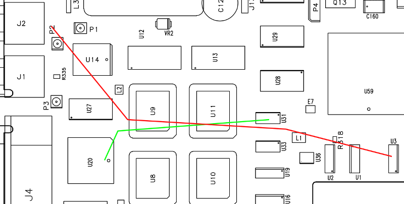 The paths of the external reference (red) and HP-IB 5MHz clock (green) The HP-IB 5MHz signal comes from U31 and travels back to U20, the HP-IB interface circuit. The external reference line goes from J2 to the area of U3. Well, there's your problem: the two lines run close to each other and the PLL seems to pick up the crosstalk signal from the HP-IB clock when no external reference is present. Doh! I just had an HP53181 falling on my lap recently so I used it to compare the REF-IN section with the 53131. The 53181 is also 4 years older, as shown by the date codes and the HP brand vs Agilent brand. There is no discernable difference between the REF-IN circuits except for small extra pads on the REF-IN line for 'P1' on the PCB of the Agilent 53131. However there is one big difference in the PCB itself. Check this out: 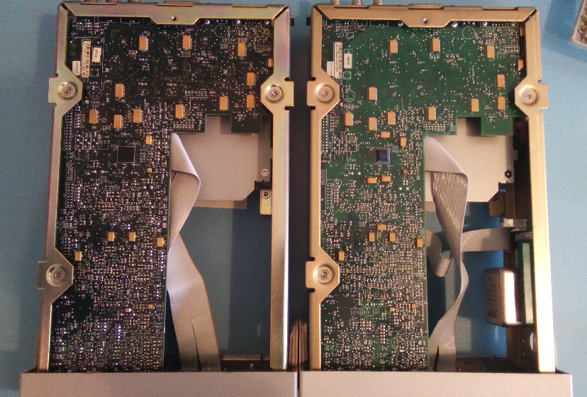 Bottom side of the PCB for the HP-53131 (circa 2001, right) and HP-53181 (circa 1997, left) The color of the PCBs seems to have changed between 1997 and 2001, which is not uncommon and really not something to worry about. Except it's actually much more interesting (and bad) than just a color change. Let's zoom a bit: 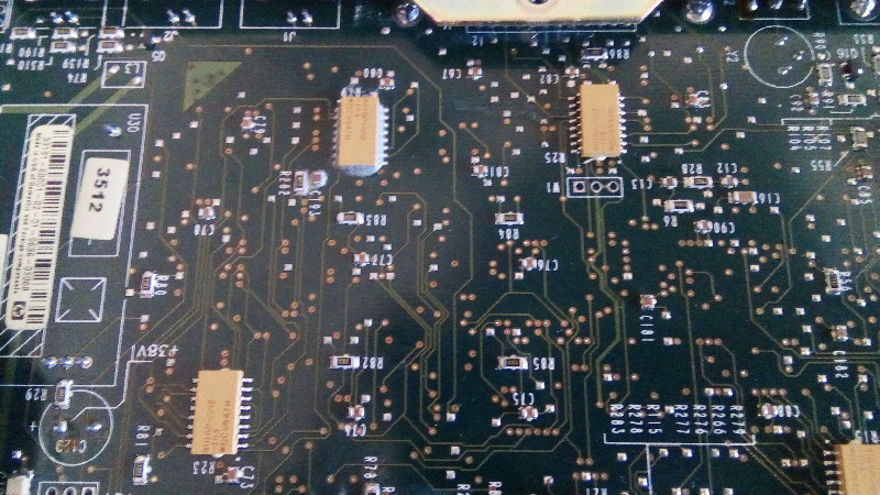 Bottom side of the PCB for the HP-53181 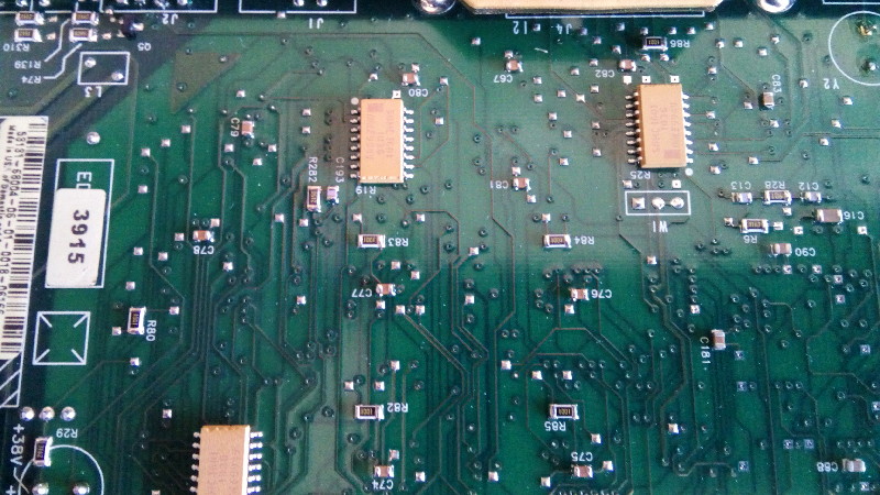 Bottom side of the PCB for the HP-53131 A seasoned electronician will notice that the color change is mostly due to the complete removal of an inner ground plane on a large area of the HP-53131A PCB: you can see 2-3 of the inner layers! And there's the real problem and why the older 53181 had no issue: the proper ground plane isolated the REF-IN line and the 5MHz HP-IB clock. But since the lines are close to each other and parallel for a long distance they inevitably experience cross-talk when no ground plane is present. Boo HP! Of course now you want a solution, and I have one for sure though it's a bit ugly (I find it beautiful but I have weird taste...) Simply put: bodge wire! Coaxial of course, I used some RG316 I had lying around. There is a large tantalum cap near the input capacitor C178 and this makes a perfect place to anchor the shield of the cable. 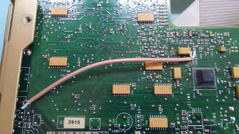 HP-53131A bodge wire to avoid REF-IN cross talk. Does it work? Does it solve the problem?? Beautifully! This is how the signal on the input pad of C178 (C178 removed) looked like with nothing connected to the REF-IN input and C178 removed (Removing C178 unloads the path between the input connector and C178, allowing the full extent of the cross-talk to be visible in clear square-shaped clock form. When C178 is present the waveform is less clear, see the first green-crt-pic of this page) 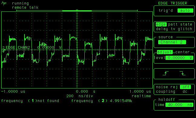 Ref-in input noise from HP-IB 5MHz clock cross-talk. Vertical scale is 100mV/div. And with the bodge wire it's just clean and flat. Finally I can say: Great Success! Now onto the second issue: parasite modulation on the external reference output. This is what the reference output of my HP-33120A generator looks like compared to the HP-53131A, using an HP53310A modulation domain analyzer: 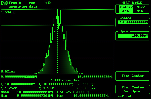 10 MHz reference output from a 33120A generator, std-dev of 6.86 uHz 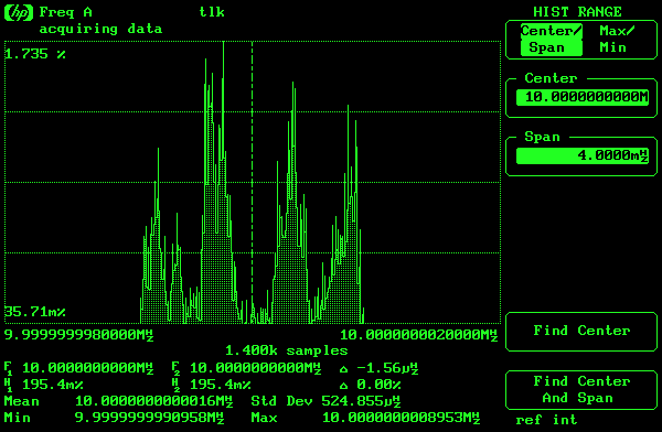 10 MHz reference output from the 53131A counter, std-dev of 524 uHz First there is obvious modulation on the 53131A output. But if you look at the span of each graph you'll notice the counter timebase output has 100 times more spread (standard deviation) than the generator's timebase output! And since we're looking at the horizontal scales, we could also check the modulation domain analyzer itself by looping back its reference output to its input. This should ideally be only a vertical line, and indeed the results are close to ideal, thus it's not a problem with the MDA: 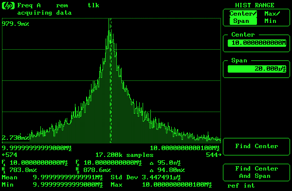 Looping back the reference output on the HP-53310A modulation domain analyzer: the standard deviation is now only 3.45 uHz I should mention that the MDA reference output was used as the reference input of the HP-33120A generator. Thus the gen only adds a tiny bit of spread to the purity of the MDA timebase signal. The 53131 counter, however, bumps it by a factor 100! At this time I have no solution for this unfortunately, let me know if you have an idea. I suspect the absence of PLL in the 33120 is the reason why it's better, though of course it then can only with with 10MHz references (no 5MHz and 1MHz external reference compatibility like the 53131A). Not sure of something could fix that modulation at the moment, but I use my own house 10MHz distribution so it's not a big deal for me. | |
| © 2024 Damien Douxchamps. All rights reserved. | |

