Small and simple pH-meter | ||||||||||||||||||||||||||||||||||||||||||||||||||||
 Many years ago I built a tiny pH meter for my former high school, the College Saint Pierre. It was based on a circuit developed at the Facultes Notre-Dame de la Paix, Namur, Belgium. This model is what has been presented on this page for a long time, and is now archived here, for there is a new version! One new version every 20 years is not too much I guess :) The older version was built as a pluggable module; for this new iteration I have aimed at limiting the required soldering and cabling within the enclosure. Thus, most components are mounted on the PCB, included the potentiometers, which makes it altogether more convenient. Speaking about the potentiometers, those are now of the same type and value in order to shrink the BOM. The new design retains all the good features of the older iteration:
SchematicThe pH meter is basically a simple gain/offset circuit with a high impedance input. Its purpose is to convert the voltage range of a typical pH probe (between -0.414 at pH 14 and 0.414V at pH 0) into something that be be easily read from an instrument, for example 0-140mV. The very high input impedance of the pH meter is critical because pH probes have a high output impedance themselves, so we must use an even higher impedance input stage for the ph meter. 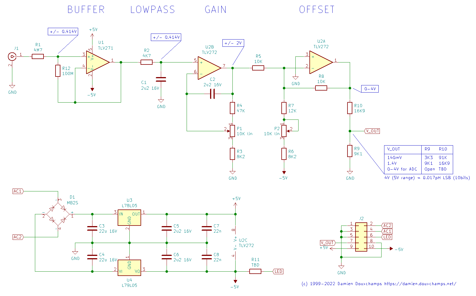 Click for a larger view. The circuit input is the BNC connector J1, which is now located on the board itself. R1 limits the input current just in case a user (or student) makes a 'little mistake'. 4M7 may seem large, but it is quite small compared to the impedance of the probe itself which is over 100M. R12 is optional; it may lead to better results with some op-amps. I have not used it in my tests. We then find the most important part of the pH meter: the input buffer amplifier U1 which here is a TLV271. Its sole (but important!) role is to provide the highest impedance input for our pH meter. Other than that it's a simple follower with unitary gain (aka a 'buffer') and it just reproduces the input voltage to its output. Multiple families of op-amps can be used but keep in mind we need a high input impedance (greater than 100Gohm). Following the follower (!) we find an RC filter (C1 and R2) which prevents higher frequencies to get into our circuit. Its cut-off frequency is set at about 100Hz (1/RC). Anything higher than that will be attenuated. After this input stage we find two op-amps for the gain and offset. Since we have a high-impedance U1 upstream, U2 can be a more mundane dual op-amp chip as long as it is roughly rail-to-rail (note the power supply is 5V and we have an output of maximum 4V, so there's only a 1V margin). U2B, P1 and the associated resistors R3 and R4 form the gain circuit. Using good-ol' op-amp formulas we find that its gain can be adjusted between (R3+R4+P1)/(P1+R3) and (R3+R4+P1)/R3, which in this case turns out to be between 3.6 and 8. Why this range? A pH probe typically returns between -0.414 and 0.414V, and we'd like to have +/-2V at the output of this stage. Thus we need a gain of 5, which sits nicely between 3.6 and 8. Following the gain stage is the offset stage built around U2A. This op-amp changes the previous stage's +/-2V output range into a 0-4V range. This stage also needs to invert the signal, since at its input 2V is pH 0 and 0V is pH 14. The op-amp is used in a mixer configuration. The pH signal coming through R5 will see a (negative) unitary gain of -R8/R5. To that we add the offset which is obtained by -5V going through R6, R7 and P2. The gain for this branch is similar: -R8/(R7+P2+R6). The extremes for P2 (0 or 10K) give an adjustment range of 1.6V to 2.5V for what will be added to the pH signal. Note that the ideal offset value of 2V sits nicely in the middle of this interval. Note that the potentiometer will not be in its middle position for that 2V offset. That's because P2 is used in the denominator of the offset formulas, leading to a 1/x dependency. Therefore there's a compromise to be made between having a symmetric adjustment range for the offset (e.g. +/-0.5V around 2V) and having the potentiometer nicely centered in the middle of the range (2V). This is not just an aesthetic issue: if the 'middle' 2V offset is obtained with the potentiometer far from its mid position then there may be little mechanical travel available for half of the adjustment range. The values I have selected in the schematic offer such good compromise but you're welcome to experiment with other values. Note that two different op-amp chips are used in this schematic. It is certainly possible to use a single quad op-amp chip as long as the input impedance is very high (more than 100G ohm) and it has a near rail-to-rail output (it should be able to output 4V with a 5V input). So you may be tempted to use a TLC274 for all the op-amps, but it only outputs 3.8V max with a 5V supply so it won't work without some modifications to the circuit (higher voltage power supply, recalculation of some resistors,...) A TLV274 could replace the TLV271 + TLV272 combination I used here, feel free to give it a try if it fits your board layout. Now that we have reached the output of U2A the pH is a linear quantity going from 0 to 4V when the pH goes from 0 to 14. If the signal is to be used by a computer (through an ADC) then we will try to match the output dynamics to what the ADC can measure. For example, with a 3.3V reference our 4V output would be a little high, so the R9/R10 resistive divider would rescale the 4V into 3.3V. The ADC would then do its magic and the final scaling would be done in software (3.3V = pH 14). But for a standalone instrument we will use a simple LCD voltmeter and we would like the display to show "14" when the pH is "14". R9/R10 can be used to perform this last scaling operation and reach 1.4V for pH 14, for example. The decimal point is not particularly important as we can set it manually wherever we want on the LCD. Some panel voltmeters only have a 0-200mV input range; in that case the output can be rescaled to 0-140mV. The voltage ranges for the signal evolve in the circuit as follows:
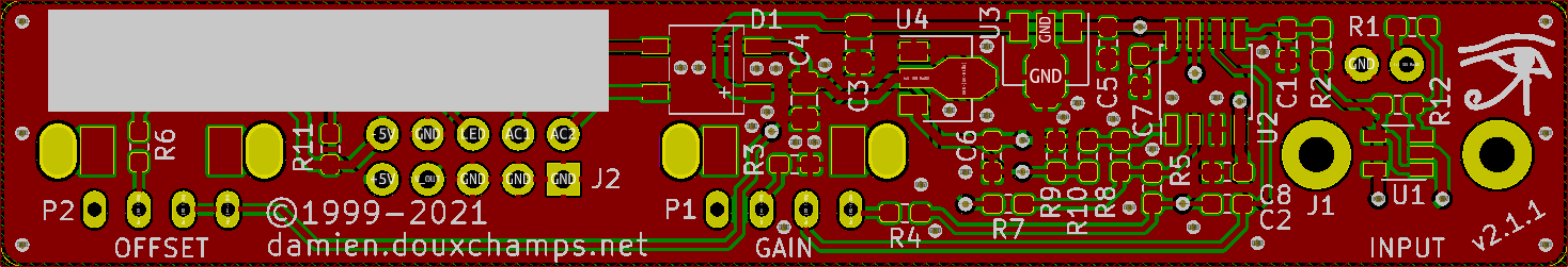
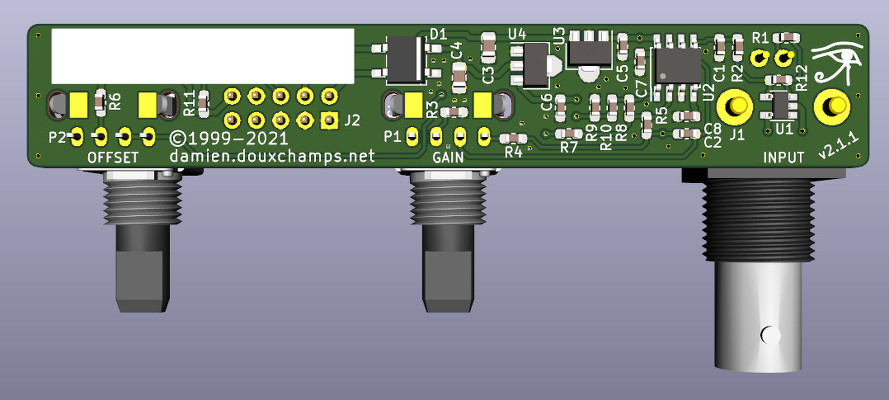
The power supply circuit is all classic stuff but there's two little things worth mentioning. First is that its capacity is limited to 100mA. You can see that connector J2 'exports' the supply rails, for example to power the LCD voltmeter. But this will only work if the voltmeter does not use too much current. Secondly, there's a specific pin on J2 for a power LED, as well as space for this LED's resistor R11 on the PCB. PCBThis new version has a narrow PCB strip that joins the three front panel bits: the two potentiometers and the input BNC connector. The size was dictated by the required separation between the elements (35mm for a comfortable use). Although quite compact it's still a 2-layer only PCB to reduce production costs. These days 1-layer PCBs can be more expensive than 2-layers in small volumes, so no point in trying to make everything fit in one layer only. Note that all SMDs are on the same side to reduce assembly costs. Similarly, silkscreen is only on the SMD side.
ComponentsThe components are standard and can be obtained from Digikey/Mouser/RS/Farnell/... Only the potentiometers are more specific. Here's a Digikey BOM for reference. Be aware that as the time of printing (January 2022) some components can be out of stock due to the global semiconductor shortage.
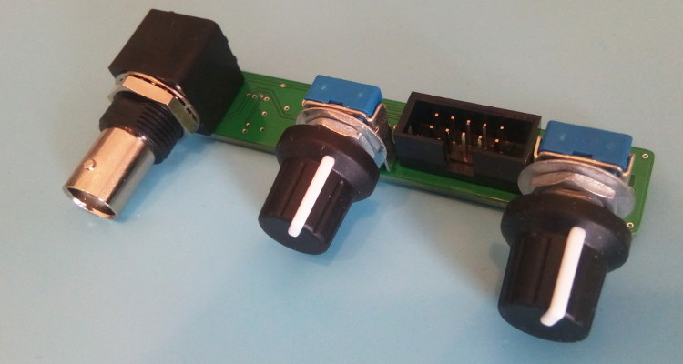
The display selected is the Lascar DPM2000S because it has a nice little pH unit segment. It has become quite expensive though: it would be cheaper to buy a micro-controller board and a display unit, like Adafruit's Feather/Wing series! If you choose to use the Lascar model anyway be sure to get the 'S' version which works on 5V. The pH electrode used in my school was the InLab 409 (IIRC) from Mettler-Toledo. Photos - the real dealThe PCB is from JLC-pcb but many other shops exist of course. The previous version made 20 years ago was from Eurocircuit, for example. I also recommend P-ban in Japan. Eagle-eyed readers may notice slight discrepancies between the PCB renders above and the real one below. Those are simply due to me moving from Eagle to KiCAD so the PCB was redone and got a new version number (2.2.1). No functional changes though. 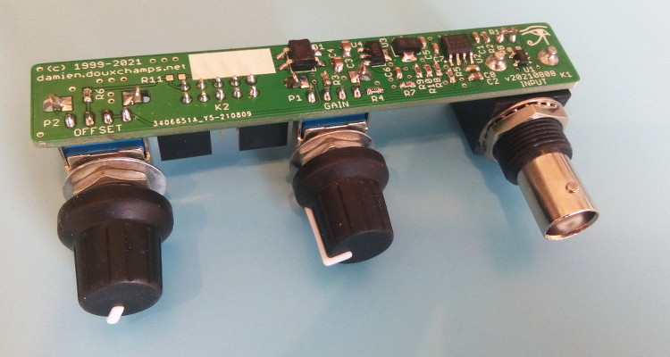 SMD side. 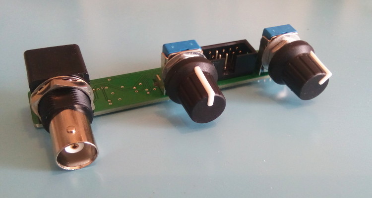 Through-hole side 1/2. 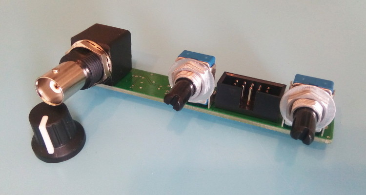 Through-hole side 2/2. Circuit calibrationCompared to the older version the calibration procedure is simplified thanks to the lack of trimmers. Well there may be one on the display, but at least the two on the PCB are gone. The calibration procedure is not difficult but should be performed with precision instruments (IOW a $5 voltmeter might not be the best idea). First short circuit the input (a 50ohm BNC terminator is a nifty thing to have for this purpose). This is essentially equivalent to having a perfect electrode in a perfect ph7 solution in a perfect world. Measure the output of U2B and confirm that it remains at zero when the gain is modified with P1. Still with the input shorted, set the offset with P2 so that the output of U2A is 2V. This setting may be a little difficult as you don't have very accurate trimmers to do it. Don't worry: just set it around 2V and then do some math... The question is simple: what should be shown by the display for the voltage found after U2A? Since 2V is pH 7 the relation is pH=V*7/2. Given the voltage that you have after U2A you can thus obtain what you want to see on the display. For example, if the voltage after U2A is 2.053V then the value that should be shown on the display is 7.186. Note that you can also choose an output value of 3-3.5V to obtain a greater display value and thus a greater accuracy in this setting. Now you can turn the trimmer on the back of the display unit until you reach the calculated pH value. And that's it: there is no other calibration needed. If you use another display or ADC then you're a bit on your own, but I assume you know what you're doing :) UsageThe pH-meter must now be calibrated with known-pH solutions before it can be used. This should be done before each use. Imagine that you have a neutral pH solution (pH 7) and a alkali of pH 9. First put the pH probe in the pH 7 solution and adjust the offset (P2) to reach pH 7 on the display. The gain potentiometer (P1) should not have any effect on the reading since any gain applied to a zero voltage will yield a zero output after U2B (remember that pH 7 correspond to a probe signal of 0V). If you see a (significant) variation when changing P1 then it means that the pH of your solution is not exactly 7. More on this below. Note also that the response of the pH meter strongly depends on the probe and the calibration should be performed with stable values only. After calibrating the offset, put the probe in the pH 9 solution (gently wipe the probe to avoid contamination of the solutions, if your probe allows wiping). Don't touch the offset potentiometer P2 anymore, instead set the gain (P1) so that the display reads pH 9. The calibration is finished! If you have different known-pH solutions, put the probe in each of them to see if you get the right value. For example, since you used a 9 and 7 solution why not try an acid of 4? If everything goes well, you should read 4 on the display (I read 3.98). If you noticed a gain-variation with P1 during the offset calibration (done with P2) then you will have to repeat the calibration several times; it means that your pH-7 solution was not really pH 7. This iterative process can diverge if you are not close to the solution. In fact, you could actually use a pH 4 and pH 9 solution for the calibration, but this would obviously force an iterative calibration process and you usually don't want that. TestingTo test the pH-meter we need a repeatable and reliable voltage source to replace the pH probe, as well as a good voltmeter. For the source we will use an Advantest R-6144 and for the voltmeter the venerable HP-34401A. I created a small python script make the source scan through various input voltages and record the output as measured by the voltmeter. First we have to calibrate the pH meter using the two knobs. I used the source at 0V (to set the offset) and -0.414V (to set the gain). Next we run the script, which results in the following table: Probe Probe Output Output [V] [pH] [V] [pH] ---------------------------------------- -0.4140 14.0000 1.4003572 14.0036 -0.3960 13.6957 1.3699007 13.6990 -0.3780 13.3913 1.3395730 13.3957 -0.3600 13.0870 1.3090771 13.0908 -0.3420 12.7826 1.2785892 12.7859 -0.3240 12.4783 1.2482592 12.4826 -0.3060 12.1739 1.2177631 12.1776 -0.2880 11.8696 1.1872706 11.8727 -0.2700 11.5652 1.1569446 11.5694 -0.2520 11.2609 1.1264467 11.2645 -0.2340 10.9565 1.0959496 10.9595 -0.2160 10.6522 1.0656152 10.6562 -0.1980 10.3478 1.0351096 10.3511 -0.1800 10.0435 1.0046105 10.0461 -0.1620 9.7391 0.9742635 9.7426 -0.1440 9.4348 0.9437585 9.4376 -0.1260 9.1304 0.9132604 9.1326 -0.1080 8.8261 0.8829257 8.8293 -0.0900 8.5217 0.8524187 8.5242 -0.0720 8.2174 0.8219249 8.2192 -0.0540 7.9130 0.7915895 7.9159 -0.0360 7.6087 0.7610849 7.6108 -0.0180 7.3043 0.7305898 7.3059 0.0000 7.0000 0.7004330 7.0043 0.0180 6.6957 0.6701730 6.7017 0.0360 6.3913 0.6396705 6.3967 0.0540 6.0870 0.6091676 6.0917 0.0720 5.7826 0.5788377 5.7884 0.0900 5.4783 0.5483400 5.4834 0.1080 5.1739 0.5178312 5.1783 0.1260 4.8696 0.4874981 4.8750 0.1440 4.5652 0.4569957 4.5700 0.1620 4.2609 0.4264888 4.2649 0.1800 3.9565 0.3961508 3.9615 0.1980 3.6522 0.3656459 3.6565 0.2160 3.3478 0.3351390 3.3514 0.2340 3.0435 0.3047989 3.0480 0.2520 2.7391 0.2743007 2.7430 0.2700 2.4348 0.2437958 2.4380 0.2880 2.1304 0.2134617 2.1346 0.3060 1.8261 0.1829624 1.8296 0.3240 1.5217 0.1524584 1.5246 0.3420 1.2174 0.1221236 1.2212 0.3600 0.9130 0.0916193 0.9162 0.3780 0.6087 0.0611100 0.6111 0.3960 0.3043 0.0307723 0.3077 0.4140 -0.0000 0.0002730 0.0027 As we can see the output follows the input down to .01 pH without an issue. Most of the error is due to the limited accuracy of the calibration step: there's only so much you can do with single turn potentiometers. But it's more than enough for our tests. The ones among you who were paying attention may raise their hand and ask what is the impedance of the voltage source I used? The goal of the pH meter is to deal with high-impedance probes, so are the previous measures realistic? Well, glad you asked: it's not realistic at all! The source impedance is low, so any op-amp circuit could have done that. But hey at least we know things work now. Let's add a series resistor with the source and see how things go. In fact, since we have a nice automated setup, why not try different series resistances impedances? Let's do that! Adding a 50M resistor and a touch-up on the calibration we get: Probe Probe Output Output [V] [pH] [V] [pH] ---------------------------------------- -0.4140 14.0000 1.4000068 14.0001 -0.3960 13.6957 1.3695927 13.6959 -0.3780 13.3913 1.3392939 13.3929 -0.3600 13.0870 1.3087925 13.0879 -0.3420 12.7826 1.2783488 12.7835 -0.3240 12.4783 1.2479842 12.4798 -0.3060 12.1739 1.2175001 12.1750 -0.2880 11.8696 1.1870151 11.8702 -0.2700 11.5652 1.1567634 11.5676 -0.2520 11.2609 1.1261877 11.2619 -0.2340 10.9565 1.0952562 10.9526 -0.2160 10.6522 1.0654396 10.6544 -0.1980 10.3478 1.0350121 10.3501 -0.1800 10.0435 1.0043871 10.0439 -0.1620 9.7391 0.9740760 9.7408 -0.1440 9.4348 0.9435467 9.4355 -0.1260 9.1304 0.9129708 9.1297 -0.1080 8.8261 0.8827386 8.8274 -0.0900 8.5217 0.8520396 8.5204 -0.0720 8.2174 0.8220187 8.2202 -0.0540 7.9130 0.7913497 7.9135 -0.0360 7.6087 0.7609262 7.6093 -0.0180 7.3043 0.7304696 7.3047 0.0000 7.0000 0.7002847 7.0028 0.0180 6.6957 0.6700378 6.7004 0.0360 6.3913 0.6395592 6.3956 0.0540 6.0870 0.6090658 6.0907 0.0720 5.7826 0.5787372 5.7874 0.0900 5.4783 0.5482600 5.4826 0.1080 5.1739 0.5177593 5.1776 0.1260 4.8696 0.4874099 4.8741 0.1440 4.5652 0.4569184 4.5692 0.1620 4.2609 0.4264178 4.2642 0.1800 3.9565 0.3961160 3.9612 0.1980 3.6522 0.3656088 3.6561 0.2160 3.3478 0.3350964 3.3510 0.2340 3.0435 0.3047614 3.0476 0.2520 2.7391 0.2742680 2.7427 0.2700 2.4348 0.2437888 2.4379 0.2880 2.1304 0.2134427 2.1344 0.3060 1.8261 0.1829462 1.8295 0.3240 1.5217 0.1524382 1.5244 0.3420 1.2174 0.1221142 1.2211 0.3600 0.9130 0.0916175 0.9162 0.3780 0.6087 0.0611194 0.6112 0.3960 0.3043 0.0311564 0.3116 0.4140 0.0000 0.0000118 0.0001 No worries! Things still work nicely. But I hear you say: 50M is not that big for a pH probe! Yes indeed, so let's push the impedance higher. I won't dump the whole table again, and instead we'll make a nice graph with the various input impedances: 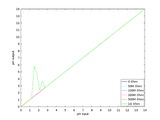 Performance relative to input impedance. Note that the pH meter gain was recalibrated each time the impedance was changed. This is because our op-amp input current is not zero, so the extra impedance results in a minute drop in voltage that is different for each impedance. This linear error can be compensated for with a little touch-up of the circuit gain. At 1G Ohm we start to see some instabilities and those were repeatable so it clearly shows a limit in the circuit or the test setup. At 2G Ohm it was not possible to calibrate the pH meter anymore: results were just too erratic. A more careful PCB layout would be required at those very high impedances (for example, guards around the input). But up to 500M the circuit is well behaved and returns great results. In fact, all 5 traces are (almost) completely overlapping. Let's see a graph of the error instead so we can zoom on what matters: 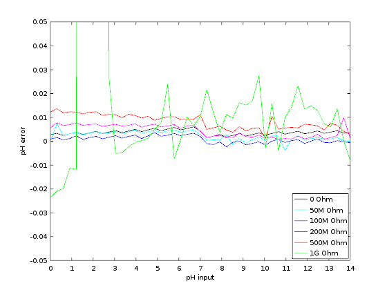 Output error relative to input impedance. With errors being all contained below 0.02pH and taking into account the fact this is a manually calibrated device, I'd say it's pretty good! In fact, looking carefully at the error graph you can see a little jump downwards near pH 7. This is when the voltage source inverts its output, leading to a tiny change in the circuit input voltage. If imperfections of a $2500 voltage source are the major visible feature of the error we can be... mmm... happy? :-) DownloadComing soon: ping me if interested! | ||||||||||||||||||||||||||||||||||||||||||||||||||||
| © 2024 Damien Douxchamps. All rights reserved. | ||||||||||||||||||||||||||||||||||||||||||||||||||||