Nikon PN-11 Electrification for Dummies | ||||
IntroductionA extension tube can be useful for a number of reasons: focusing closer, getting higher reproduction rations, and, in the case of the PN-11, provide a tripod collar. Unfortunately Nikon has not yet upgraded its old trusty MF tubes by a version that would include all nowadays goodies: AF coupling, aperture selection on the camera body, and last but not least all the electic contacts to support matrix metering, AFS,... There is no way you can use AF or matrix metering with the PN-11 (note: recent D2 bodies might meter). Not to mention the F80, D100 and other non-pro body users who can't use their camera with the tube since the body requires electric contacts with the lens. Not allowing these users to enjoy manual lenses is a (commercial) crime in itself, but let's go on with the PN11... There is actually a third solution to this problem: forget Nikon and go buy the Kenko tube set. Once you get the tubes in your hands you immediately feel the difference in buit quality: Nikon's PN11 is rock solid (full aluminium), Kenko's are plain plastic and while they are of course lighter you just don't want to hang your F5 to this. Besides, a quick check will show you that the Kenko tubes have a vignetting problem with some lenses: you'd better try every one you own to be sure about which lens can be used with them, at which focusing distance,... Oh, and don't forget to try *every* combination of tubes, close-up lenses and teleconverters with your lenses. You've got the idea... For example, I tried stacking the two small kenko tubes behind an AFD 105/2.8 and some ghosts appeared at the bottom of the image. (Inverting the tube order fixed the problem, but how convenient...) So one day, one crazy guy wondered if it was possible to get the best of both worlds: the strength and the collar of the PN-11, with the electric contacts of the Kenko tubes. I have to say here that this guy also tried quite a few ways to get electric contacts from Nikon, but they always refused: We don't want customers to modify the equipment or We want to keep the same best quality for Nikon equipement and therefor can't sell spare parts. Even calls to Japan (in Japanese!) were unsuccessful. Ironically, this led me to use the not-so-good Kenko parts on my PN-11... How can the PN-11 be enhanced?The original PN-11 provides two mechanical couplings: one for the detection of the maximum aperture setting and one for the classic AI indexing. The original Kenko tubes provide 3 mechanical couplings: the ones of the PN-11 plus one obscure additional coupling identical to the aperture coupling and placed symetrically across the tube. It also provides 7 electrical contacts. At last, there is a little tab on the camera sides to force the body to recognize that the aperture ring on the lens is set to the maximum. I'd like to say that this forcing, which is not a coupling, might be dangerous: you could very well have forgot to lock the aperture ring and the camera would not know about it. That means that if you press the shutter asking for an aperture smaller (say, f/32) than the one actually set on the lens (say, f/16) you might have some camera damage. The solution I propose here uses the PN-11 as a base with the following modifications:
ChecklistThere is quite a number of tools you might want to have to do this PN-11 mutation:
Some recommendations:
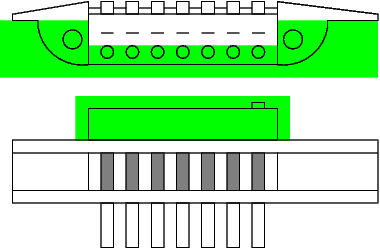
STEP 1: Removing the contacts from the Kenko tubeFirst we want to remove the contacts from the Kenko tube. Choose the largest tube, the 36mm. The reason for this is that the electic wires will be longer and easier to install. Besides, you will have a nice 52.5mm tube that will replace that crappy one so you don't really care about the big one. Note: if you use the smaller models you will be forced to lengthen the cable (see below). Remove all screw that you see. Then remove those you did not see. Do not remove the little screw on the male contact block, just under the contacts. At this point lots of things will fall appart. Don't worry, it's the bloodiest part of the surgery. The unsused parts of the Kenko tubes are shown on fig.1. 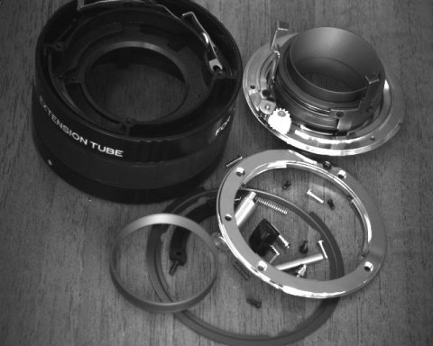 Fig.1:What remains of the Kenko 36mm tube The female contacts can be removed easily, but you will quickly realize that you can't remove the male contacts (the studs bar) because the wire at the female end is glued to the tube body. Carefully insert a small knife between the contacts of the cable and the body and move it along the contacts to slowly unglue the cable. It's not a hard glue, just some sort of scotch. You have know in your hands (and most probably spread across the table, if not the room):
STEP 2: Open the PN-11Just remove the screws on the camera-side mounting flanges (5 similar screws). Do not remove any screw of the male end that has its axis perpendicular to the axis of the tube. Keep the screws in a *very* safe place (screws are like ants: you know where you put them but never where to get them). Remove the mounting flange and the narrow plastic ring under it. Unscrew the lens-side flange (4 screws identical to the 5 of the camera side). Put the screws with the other 5 from the camera side. Remove the PN-11 hood on the female side. Carefully remove the inner tube and the larger tube around it. Precautions during the whole surgery: take care not to bend or damage the aperture coupling on the camera side and take extra care not to scrath, dent,... the inner tube liner. 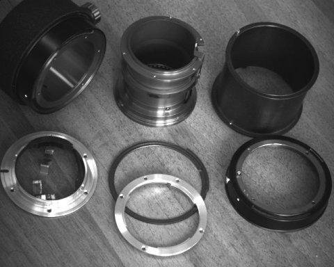 Fig.2:The seven parts that make the PN-11 Spread the 7 parts on the table. Put the long spring aside with the screws. Identify who's who. Rebuild the PN-11. Figure out how mecanical couplings are working. Do this a couple of times to get familiar with the hardware. The part are, from lens to camera (fig.2):
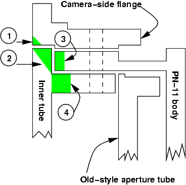
Before you do anything bloody to these parts take another look at them, turn them around, look at how they're built. The modification involves removing matter, and this is operation can't be reversed: if you do something wrong you might need a new PN-11... STEP 3: Secure the areaIf your significant other is there, kindly ask her/him to leave the room. If your kids are still there, kindly *kick* them out ;-). Kill the phone. Put your safety glasses on. You are now in a secured, asceptic area, ready to start the surgery. (Do not lock the door, you might need some medical attention if something goes wrong. A surgeon is not a medic.) STEP 4: Making a pass-through for the cableA cut across the PN-11 on the camera side is presented below. Four changes must be performed as repsesented on fig.3. Fig.4 thru fig.6 will guide you further.
Fig.3:The four modifications necessary for the cable passthrough. You will have to gently file the flange (1) and the inner tube (2) to let a space for the cable. Just smooth the angles to 45 degrees slopes in both cases. The width of the filing should be enough for the cable, say 7mm. The parts to file-off are shown in green on the image. Once this is done, put the flange and the inner tube together and check that the cable can go through. By the way, when you file, always make a clean smooth surface or edge. Remove all little alu scrap around the holes. 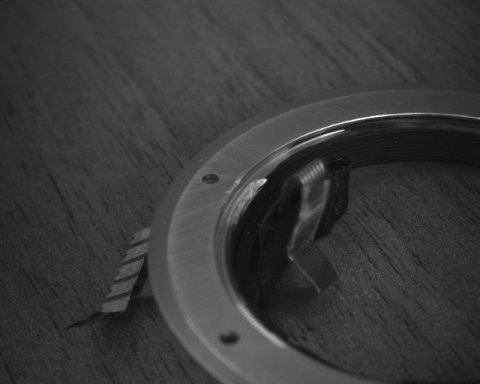 Fig.4:Filed region on the male flange 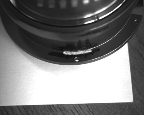 Fig.5:Cable passthrough, looking towards the camera 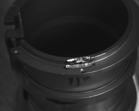 Fig.6:Cable passthrough, side view 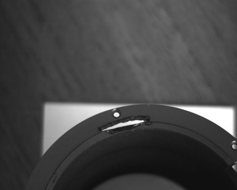 Fig.7:Cable passthrough, top view First serious work: you now have to make an oblong, arc-shaped hole between a screw hole and the file you just did on the inner tube (4). I drilled several holes, then joined them together by drilling sideways and finally filed here and there. Other methods can be used. Just make a nice 9mm-or-so long hole. Refer to the pictures for details. At last, you must also file off the tube body on 7mm (3), as on fig.8. Once again, refer to the pictures. When this is finished, check that the cable can go through all this channel without troubles. Screw the PN-11 body, the flange and the inner tube and check that the cable can still move inside its hole. To let the cable go through the oblong hole you drilled, fold 3 contacts of its end on the other 4 contacts: now it can go through the 9mm hole. Don't do this too often as you might break the cable. 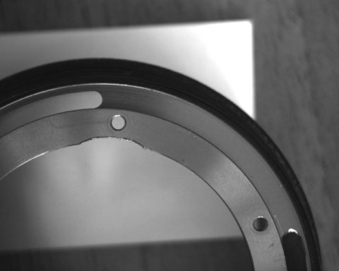 Fig.8:Filed region on the PN-11 body STEP 5: Shaping of the male contact blockThe male contact block is a ring, but you don't want that because this ring might cause vignetting. You just want the contact block, nothing else. So just cut the ring away and keep the contacts. You will also have to flatten the block as seen on fig.9 below to ultimately scare off the vignetting deamons. 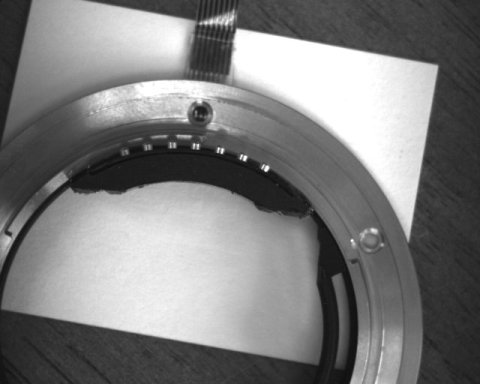 Fig.9:The shape of the male contact block STEP 6: Get some beerDon't stare at your PN-11 for hours. Get some beer. Call you wife/husband, have some fun. Whatever. But take a rest because your wrists will need it for the next file session. STEP 7: Shaping of the female contact blockCut the contact block so that its height is limited to the height of the engagement slopes (on the sides of the contacts). That means removing quite a lot of plastic, I know. Use a rough file, then a fine one. Remove also all the plastic that is on the outter side of the little holes on the contact block. Remove the holes used to attach the block with screws. Fig.10 below shows the parts to remove in green.
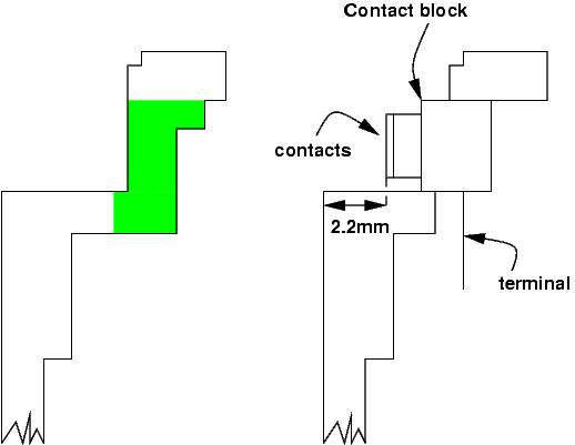
Fig.10:Reshaping of the female block STEP 8: Make a hole for the female blockThis is serious fun. First, you have to allign the hole you make along the circomference of the tube. Then you have to file and drill a lot to get the right hole. Then you have to check it, clean it as usual,... It took me at least two hours to do this: gently file 0.1mm on the right, try to insert the contact block, check its alignement, decide to file left,... Just don't make it too wide. Fig.11 thru fig.15 show how it should look like once the contacts are glued (sorry, no pics before gluing!).
Fig.11:Cut across the tube, showing in green the parts to be filed-off 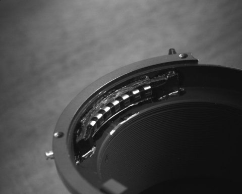 Fig.12:Cutting the tube for the female block, view from inside the tube 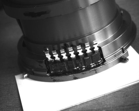 Fig.13:Cutting the tube for the female block, outter view 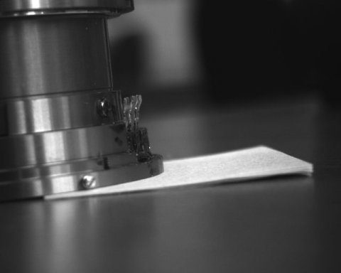 Fig.14:Cutting the tube for the female block, side view 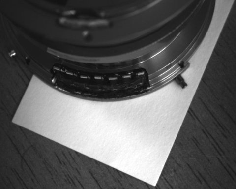 Fig.15:Cutting the tube for the female block, top view When the contact block tightly fits in the hole (you will have to insert it solder-pins first, from the inner side), screw back some PN-11 parts and try it on a Kenko tube. Are all contacts OK? No shorts on adjacent contacts? Not too much friction? No mouvement of the block inside the hole? Check, double check and triple check this. File the contact block a bit more if necessary. Check and Re-check in an endless loop, because the next step is... STEP 9: Glue time!This is something you should do before glueing anything: check the quality of the glue. Try to glue together a plastic leftover from the male contact ring and some aluminium. See how long it takes to harden. Check how it resists heat: some two components glues melt like ice-cream when you heat them. The halogen lamp on your desh is perfect to radiate enough heat at close range (5-10cm) for this test. Check that the glue does not melt plastic. Practice the mixing phase, try to get a very homogenous mix. When you're ready, take the toothpick you used for mixing and carefully apply glue on the outline of the hole. Promptly insert the contact block, position it correctly if there is a little play. Don't be hasty in trying your contacts, just let it harden for at least 2 hours. When its already quite rigid and you can hardly move it (time depending on your glue, usually 2-3h) you can make a contact test with a kenko tube. Check everything is fine, otherwise do all you can to remove the contact block. Good luck! You will have to clean the hole for glue and start over. Wait at least 24h before using it. STEP 10: AI to 'f/max'If you succeed to reach this point unharmed and you PN-11 is still in one piece (well, you know what I mean...), then this is going to be a piece of cake! Just drill the PN-11 body and hood as shown on fig.16 and fig.17. The size of the hole on the body does not matter, just make it large enough. The size of the hole on the hood will determine the travel of the big inner tube and drilling must be a little bit more accurate. Don't worry though, +/- 0.1 mm will not change everything. Check with a lens to see that the part moves correctly and transfers the f/max tab to the camera side. You don't need the long spring anymore, but keep it if you want to go back to the AI mechanism. 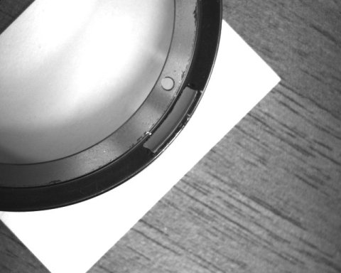 Fig.16:The little hole on the PN-11 hood for the f/max link 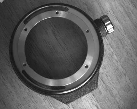 Fig.17:The hole on the PN-11 body for the f/max link STEP 11: extending the inner cableYou only need this if you want to be able to open your PN-11 when everything will be finished. That's a good idea to do so, but it requires some strange parts that you might not have. If you can't do it the solution is to first make the electric connection through the PN-11, and then to glue the male contacts. In this case any little cbles will do, you just need about 2cm of 7 conductor flat ribbon cable, as flexible as possible. Now if you want the 'really right stuff' you have to first make the cable bigger, then glue the male contacts and finally solder the cable to the female block while rebuilding the PN-11. Let's see how to extend the cable... First you will notice that there is the aperture mechanism in the space where the cable go. Since you don't want to mess with that you will have to use an extremely flexible cable extension. My recommended solution (the one detailed below) involve using a cable identical to the Kenko cable. The pitch of this cable is 0.02''. You will need 3-4 cm of such cable. Where to find that? A good source for such cables is a dead hard drive: there is always some flat flexible cable from the drive head to the assembly. I was lucky to find hard drive freak show a cable with 10 conductors, 8 of them having the right pitch. I just sliced the 7 conductors I needed with a cutter. Once you have the cable and you are sure it's the right pitch (superpose the cables and look at a light through them to check it), cut the Kenko cable in two parts. Remove the coating of the cable on the bright copper side, until 5mm are perfectly clean of this coating. Do this by scratching the cable with a cutter blade. Do it slowly and nicely. Then put a very little solder on the exposed end, as little as possible, just to have the contacts tinned. Watch for shorts by looking at a light through the cable (fig.18). I would strongly recommend you make tests for this on a spare cable. Results can be very bad if the conductors are not properly exposed. 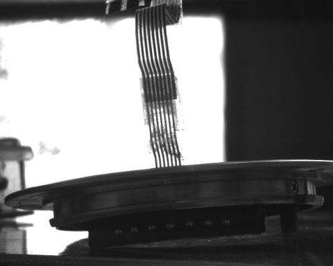 Fig.18:The soldering zone, as seen through the cable Now you have 4 exposed ends facing upward on your desk. Flip the extension cable and put its ends on to of the Kenko cable ends. Look at the finished cable picture below to see how the cables are joined exactly. Put some weight on each cable so that it does not move, then carefully allign the two cables so that the tinned parts are overlapping each other. Now take your soldering iron and press it on area to be joined. You will press on the plastic side but heat will be easily transfered to the solder below and all contacts will be soldered in one time. Use your multimeter to check for good contact and abscence of shorts. Do it again for the other end of the extension. You should get something like fig.19. Note that the flat cable has been given a strange shape to fit inside the tube with minimal friction with the rest of the moving parts. This is not mandatory. I would recommend, however, that you put a little scotch coating on the soldered sections. 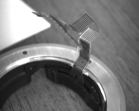 Fig.19:The extended cable At last, you can see on fig.20 how to bend the cable to enter the cable pass-though. The unbended side shoud go first in the hole, then the bended side. 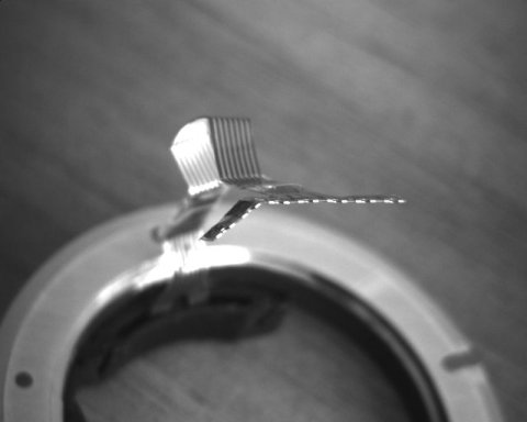 Fig.20:Bending the end of the cable to go inside the passthrough STEP 12: Glue the male contactsWARNING: you should first re-build the PN-11 and make the electrical connections if you are not using an extended cable!! Align the central contact with the screw hole. Check that the screw hole, the contact and the white dot of the collar are aligned. Look also at the alignement of your other Kenko tubes. This male contact are the weakest part of the conversion. To add more strength to it you should depolish the gluing zone of the contact block with sandpaper. Then put some glue on the contact block, under the slightly protruding line (the area you just depolished). Don't put glue over the little screw. This line should remain on top of the flange (see fig.21 and fig.22). Once again, look at how your Kenko tubes are built. Glue it and leave it alone for 24 hours. 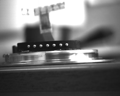 Fig.21:The glued male contact block 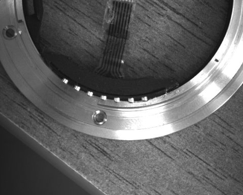 Fig.22:The glued male contact block, top view The next day, check that contacts are good. If they're not, you are in a bad position: you'll have to remove the contact block, probably destroying it. That means another tube you will ruin. Since there is no glue on the little screw, it will still be possible to remove the extended cable and use it with other contact block. Extreme heat or cold can destroy the glue, you might try that to remove the faulty block. STEP 13: Put it all together!First put the inner tube in the 'f/max' (or AI) big tube. Put the two tubes together in the PN-11 body. Put the plastic ring in its right place on the camera body side. Pass the contact cable through the channel, over the aperture mechanism of the inner tube and solder. I know passing the cable is a little bit difficult: take you time. Next check that the big tube is rotating properly and that it is used as you want ('f/max' or AI). Then screw everything back and test your new PN-11. Good job! And now of course, go out and use it! 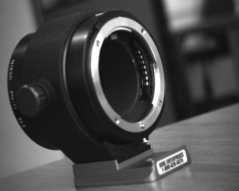 Fig.23:The Electric PN-11, lens side  Fig.24:The Electric PN-11, camera body side Links
| ||||
| © 2024 Damien Douxchamps. All rights reserved. | ||||
