Quiz-Show circuit | |
|
This project is a useful hack when it come to make your own quiz-show, or maybe just train your team for a real TV show or even simply to have fun... building it. The device solves the problem of knowing who pushed the mushroom first (there's always a big mushroom in this kind of games, right?). But it goes further: it gives you the order in which all participants have pushed the button. This allows different scenarios, like testing reflexes. It's also fun to analyse because its a clever little hack... (IMHO) The circuit was designed and built in the late 90s and is still used today to train the team of my former college for the TV game "Génies en Herbes" which was aired for several seasons on the Belgian TV. Out of the hundreds of college teams they ended at the second place, partly (I hope) thanks to this circuit that allowed them to train themsleves in real 'quiz-show' conditions. At the beginning I was asked to re-design a similar circuit which was entirely built with electromechanical relays. Given the switching time of those devices, it was quite common to have a tie between two persons (i.e. two persons would be number one). The relay circuit was built in a mains distribution box: clearly the work of an electrician... ;-) At that time I did not build PCBs so I don't have a layout ready. I do have a schematic to propose, though. The circuit was built entirely on the back of a 4-inch 7-segment LED display. Given the limited track pitch of 1/10'' and the bulky DIL components this was a very, very packed design which was planned entirely on paper. Ah, the good old days... Before looking at the schematic, let's have a quick peak at the key features of this project:
SchematicThe principles of this circuit are quite clever... Of course, since I invented it ;-) First it is completely asynchronous. There is not even a clock for each pusher unit. That will yield a very high discriminating power and ultimately result in a near-impossibility to have a tie between to persons: one will always be before the other. In hours of testing and use, we have never observed a single tie. The system is composed of a power supply unit (PSU) and several 'pusher' units that are daisy-chained with a 4 conductor cable. The PSU is a very simple thing: transformer, rectifier, capacitors and a regulator. It is equiped with a reset switch S1 which is filtered (C8, C7, R2) to avoid bouncing/noise on the line. The reset circuit also performs a reset on each power-up cycle thanks to C9. Nothing even close to black magic, but the rest is more interesting... 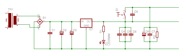 The pusher (or mushroom) unit is a bit more complex with 5 ICs, the LED display and a few components thrown in for good measure. I will explain the schematic in two cases: the first one is when the pusher switch is pressed, the second one is when a pulse is received from another pusher unit. 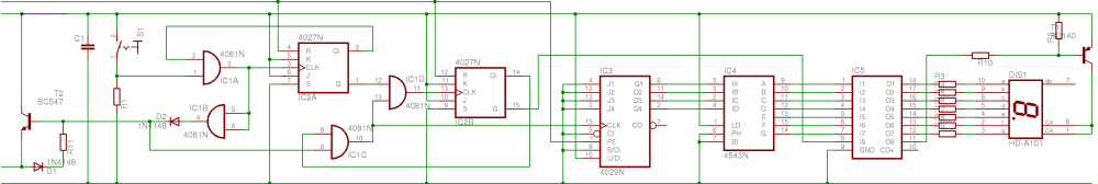 Mushroom pressed In the first case (the case where you are smarter than others and are the first to press the button), the AND gate IC1A receives a positive input from the switch. Its second input is driven by the flip-flop IC2A output Q/ which is high at boot time. IC2A therefor receives a high signal from the gate IC1A which in turns toggles its output: Q is now high and Q/ is low. This low Q/ applied at the AND gate IC1A blocks its output. If you followed me, you have probably realized that a pulse has been created at the output of IC1A. The pulse duration is equal to the propagation delay in IC1A (x2) plus the one in IC2A. This is typically a few nanoseconds. The pulse follows two routes: one left and one right. On the left, it is sent to T2 via IC1B and D2 (for insulation and short protection, respectively). T2 will drive the line to the high level for a brief moment and this is broadcasted to all other mushroom units. The pulse has several effects on the right. First note that at this point the output Q/ of IC2B is high (we're still after a reset here), and the output of IC1C will therefor reflect the pulse grabbed after D2. This pulse increments the counter IC3 and is also sent to toggle IC2B via IC1D. The latter will transmit the pulse since the output Q of IC2A is high. Once IC2B is toggled, its output Q/ is zero and will block IC1C, resulting in no counting pulses being transmitted to the counter anymore. It will also prevent IC2B to change since no output on IC1C means no output for IC1D either and thus no clock to change IC2B. The circuit is blocked until the next reset. Further downstream, the high output Q of IC2B enabled T1 via IC5 and the display switches on. The number 1 is shown since only one pulse has incremented IC3 (see previous paragraph). IC4 is there to change the binary counter output to a 7-segment display output. The circuit is now locked everywhere: IC1A, IC1C and IC1D prevent any change until a reset is performed. To summarize, we can see that when the mushroom button is pressed, the circuit switches the display on, increment the counter and locks itself. This locking capability is important since you don't want people to be able to push several times on the mushroom: this would create an endless mess! Pulse received on the line What happens if someone presses his mushroom before you? As we have seen, a pulse is sent by a unit whose mushroom is pressed. This pulse will arrive via D1 and R11 in your unit. D1 avoid the bypass of T2 in the case detailed above while R11 cancel the feedback loop that could be created with T2/D1 (and would completely block the line). The pulse then reaches IC1C. Will it go through it? Yes, because the output Q/ of IC2B is high (after-reset-state). Hence the counter will be incremented. Will the pulse propagate further? No, bacause the output Q of IC2A is zero. The circuit is thus not locking itself because nothing reaches IC2B. Which also means that although the counter has been incremented, nothing will be displayed (T1 blocked). You can see by now that if N persons push their mushroom before you, your display will show N+1 when you push your button. Which is exactly what we want! Note that I haven't detailed the values for several components, actually all R/Cs in the circuit. I believe it's not very difficult to do that and besides you will need to adapt these values to the LED display that you choose. The only resistor requiring a comment would be R11 as it has a specific function. Halas, I do not have its value at hand right now. But I'm sure you can experiment with different values until it works (which is basically what I did anyway) That's all folks! :-) | |
| © 2024 Damien Douxchamps. All rights reserved. | |

