Imagenics WBD-14F conversion for 10MHz house standard distribution | |
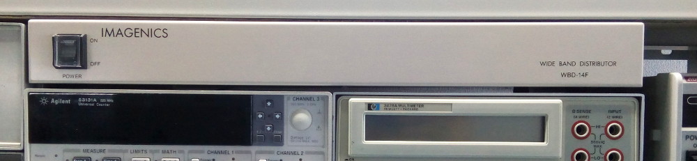 The Imagenics WBD-14F in a most unnatural habitat. This fellow normally lives in AV systems racks but somehow got lost and ended up in a geek's lab. Once you start to have a few generators, counters and other test gear that accept an external frequency reference you soon want to share the same reference clock between them, and that means you'll need to distribute that clock signal. This is commonly known as making your own "house standard": a 10MHz line that connects all your instruments. This could be done by daisy-chaining the various devices, as many will have a reference input as well as an output (e.g. my 33120A, 53131A, 53310A). Unfortunately some only have a clock input (5334A, 3325B) so that's not a viable solution. In addition, daisy chaining means that the reference will go through a lot of PLLs and in the end gets a bit distorted, as I learned with my 53131A counter that doesn't have a very clean PLL output. HP did sell a clock distribution amplifier back in the day when it also made reference clocks (5061A / 5071A cesium awesomeness!). For example, the HP 5087A or the newer HP 58502A. But those are often either fetching high prices ($500 and up) or are a bit outdated (the 5087A is in most cases only designed for 5MHz references). Thus 'the community' has been looking for solutions to keep our time-nuttiness happy. The popular option is to get a video distribution amplifier: they are equipped with good'ol' BNC coax inputs, have a large bandwidth (>200MHz, plenty for out 10MHz reference) and since they are mostly obsolete in these days of digital video they can be obtained pretty cheap. Extron is a popular brand to build conversions on, especially after a popular video was released on the subject. But I'd like to make a better, or at least cleaner job. The model in the video is a bit clunky, and has the huuuge problem of not being rack-mounted which in my book is a definitive no-go in terms of coolness. So what do? Well other rackable 1U models exist by the same manufacturer, and they can be had for just as little money ($30). Their clean front panel offers a lot of possibilities for future additions and customizations, but they have a tiny little issue: the device is about 2cm wider (44cm) than HP rackable units (~42cm). All fit nicely in a rack, but not on the shelves I have today. So to have a nice fit like toe one on the pic above I had to find another manufacturer. Plus, the current auctions for Extron devices were in the $50 range. Boo. So it's about time that I finally introduce the Imagenics WBD-14F wide band distribution 1U rack. Nice cream color to remain assorted with HP devices, proper width, sold with rack ears (not shown on pic) and I could get an old-stock unused item for $25 shipped! Plus it's made in Japan and has a nice video-studio-style power switch. It does have one flaw (for now, more coming later...) : it's only 100V compatible, so no switching PSU inside. Here's the device on the bench before the surgery starts, which is also a good time to have a look at its rear panel: 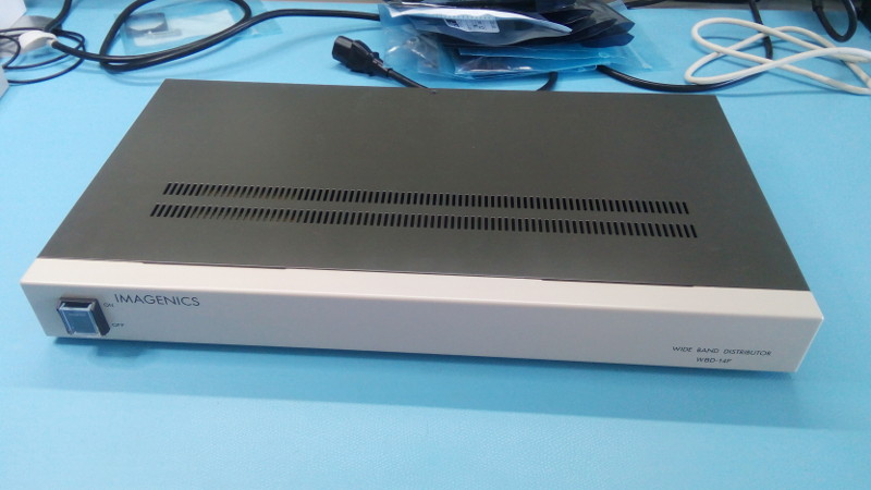 The Imagenics WBD-14F on the bench 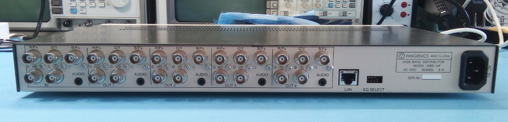 The Imagenics WBD-14F's rear panel: BNC goodness! Before you ask: yes that's a network RJ45 right there, and no I have no idea what it's for. The user manual only mention "for future expansion" and the port doesn't seem to support DHCP. Other documents like the spec sheet and the catalog/pamphlet are not providing any information. Looks like some hacking in perspective! Anyway the important bits to hack are on the hardware side:
Time to open this baby... First it's heavy and made entirely of sheet metal. The entire lower 'cream' part is one single bent/spot-welded sheet, which is not going to make drilling the front panel any easier: 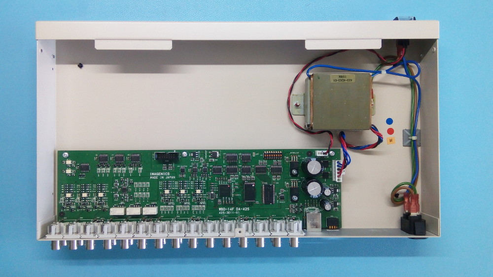 Inside the Imagenics WBD-14F. A bit empty? Nothing to see here, move along? Not quite... As expected the 1U rack is rather empty: a transformer, a few AC cables and a single PCB. Let's have a closer look at the latter, which is the only really interesting bit: 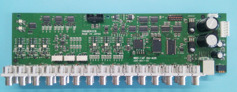 The Imagenics WBD-14F's main board, before surgery It's here things start to look a little 'funny'. First we have 4 video outputs with 3 channels per output so we should see 12 amplifiers, one per channel. Evidently those are nowhere to be seen. The back of the PCB has no components BTW. It turns out Imagenics has decided that sharing a single amplifier per color channel is enough, something rather surprising for a device of that grade/price (new this costs $1000). OTOH it's also what the Extron has so maybe it's not that abnormal. Let's do a quick mapping of the board puzzle: 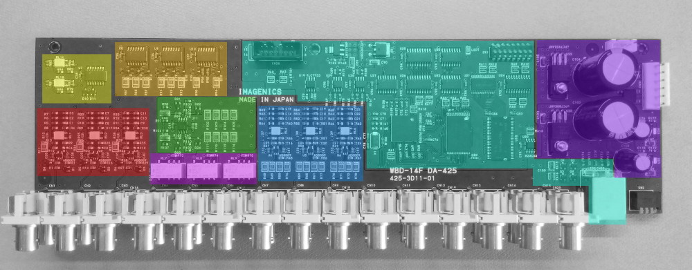 Board function blocks
And that's it! 50% of the board is used up by seemingly unnecessary and expensive digital electronics while there's only a single amplifier shared for each video channel. Strange construction for sure! Then again it's pretty clear at this point that I don't know much about video devices. So let's concentrate on the 10MHz reference modifications instead, shall we? ;-) And what better way to start than to reverse-engineer the video/RGB circuit? Here's the areas we're interesting in (the red, magenta and blue areas as shown above) and what the schematic looks like to the best of my knowledge, in all its KiCAD glory: 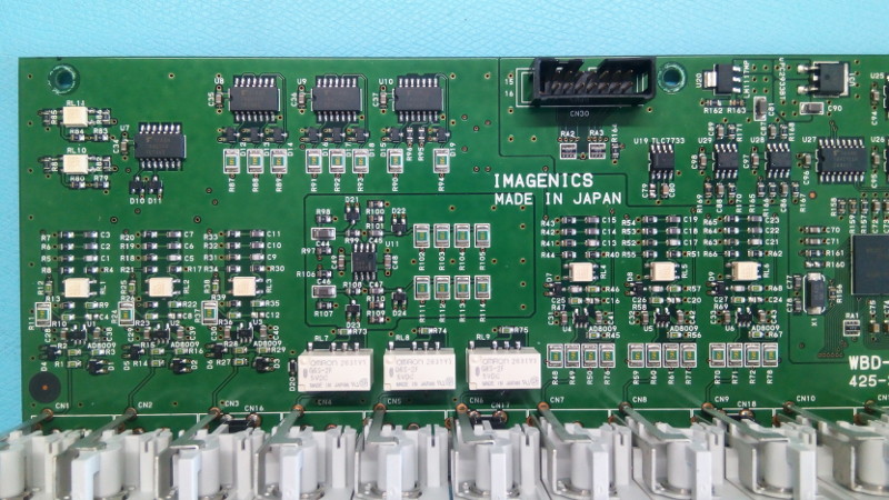 The Imagenics WBD-14F's main board video section (with some audio bits thrown in) 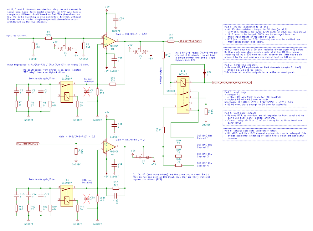 Video in/out sections schematic, click for a larger PDF version I've talked about most of the elements so I'll let you probe deeper if you feel like it ;-) The important bits are the notes in the blue boxes on the right side of the sheet: those detail the changes to make this box finally do what we want it to do:
Note that I haven't modified the H/V sync circuit much: only the output impedance was updated. The two sync channels can be used to distribute slower timing signals like a 1PPS from a GPS, for example. Their two inputs could also be merged if needed. A front-panel BNC for a 1PPS signal would also be handy... After the modifications this is what the board looks like. Note the black 50 ohm resistors replacing the green 75 ohm ones. At the end of the mod you'll have a few green resistors for your parts drawers... One last thing: this device does not have a mains fuse, nor does it have any other fuse on the main board. I recommend to add an inline fuse just after the mains socket. Not sure how this can pass certification, but hey maybe pro equipment like this does not have the same rules as consumer items. Still... For the fuse holder you can use Digikey part 01500274ZXU-ND. 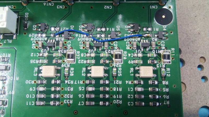 Modified input section 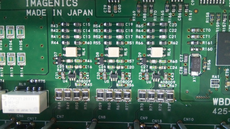 Modified output section (only the larger resistors changed) 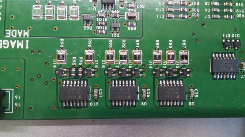 Modified Sync section (only the larger resistors changed) 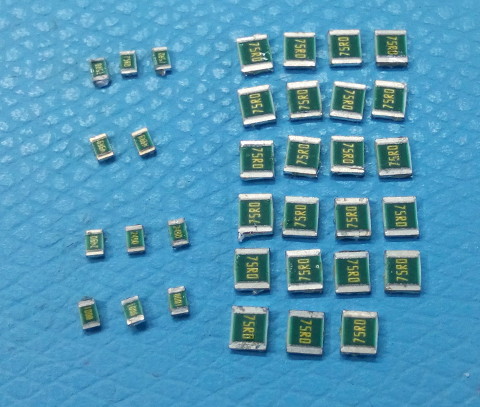 Salvaged/updated/removed resistors 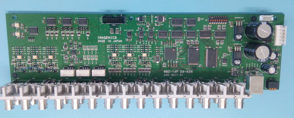 The entire board after the modifications were performed And now it's... testing time! I connected 4 BNC cables to random outputs (4 out of the possible 12) and piped that in my scope. The results look kind of nice but not perfectly in phase, as one could expect since there is no line-length equalization. The time/phase shift is about 800ps, which at 3e8m/s means a length difference of 24cm at worst. This is quite interesting since it's roughly the length of all the BNC connectors section in the back, nicely explaining the phase shifts. Fixing this would require a new board, which may actually be a great idea since all the hardware like BNC connectors are ready to be salvaged from the unit, bringing the cost down quite a bit. Maybe some day... 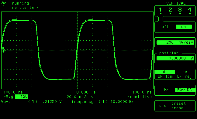 Four random outputs on the scope 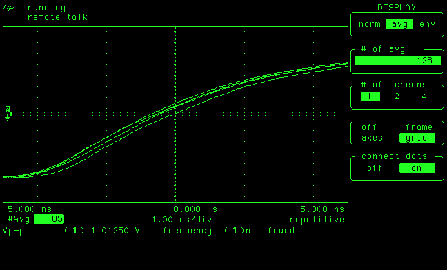 Zooming on the previous image to get a better idea of the phase shift Next steps are to drill and install the front panel outputs. I would also like to integrate a GPSDO inside: plenty of space for it and it would mean I don't have to use my 53310A MDA when I want accurate timing (my 53310A has the high-stability, always-on timebase option so that's what I use as house standard). Finally just for kicks I'd like to probe that RJ45 and figure out what it's for, but not being a network kind of guy I'll wait for insightful comments to start digging deeper. Do get in touch if you have ideas! | |
| © 2024 Damien Douxchamps. All rights reserved. | |

