Parametric Audio Equalizer | |
|
This project is based on the parametric equalizer proposed by Elektor in the 1980s and later published in the book "Creations electroniques" in 1986 (Publisher: Publitronic). But what is a parametric equalizer I hear you say? The familiar graphic equaliser has only one control per band: the gain. As a result many bands are needed to adjust the sound to your liking. A parametric equaliser is much more versatile, with 3 controls per band: the gain, the frequency and the bandwidth. This allows the parametric equaliser to get away with using only a few bands, typically two or three. A good parametric equalizer also includes controls for the top and bottom end, and those filters have a selectable cut-off frequency. You will find names like "shelf" eq or "Baxandall" eq for those controls. The original design involved three stereo potentiometers per channel, which means a lot of cables from the front panel to the circuit board: 5 lines on average per pot, times 3 pots/filter, times 6 filters (stereo equalizer). Yep, that 90 wires! Yikes! And the Baxandall tone controls are not inven included in that total. It's quite tiedous to build and in my experience very prone to noise from within the enclosure. To solve these problems and make the unit more compact the potentiometers have been moved on the board, all the components are SMDs and, lo and behold!, the board is double sided. Yep, the original board was single sided; welcome to the 80s when you had to get the acid bath out to create your boards. In addition, the original board layout contained a nice ground loop, which is not ideal in an audio device. Since more than one filter is needed it would also be nice to be able to nicely cascade the PCBs when they are placed next to each other in the enclosure. To this end the inputs and outputs of each board are facing each other, only requiring a small cable or even a solder bridge to link all filters together. Like God(tm) intended. Other modifications were necessary for the values of a few components. This was prompted by the decision to use off-the-shelf stereo potentiometers and limit the pots type to two only: 10k lin stereo with detent and 10k log stereo without detent. This reduces BOM costs quite a bit given the relatively high costs of potentiometers in this project. The potentiometers selected in previous revisions was the RK14K124 line from ALPS but this has now been 'upgraded' to the Bourns PTV112 series which has more alternatives when it comes to shaft lengths, taper and values. Although it's still hard to find some of them, and thanks to Murphy it's of course the one we really want (threaded bushing version are hard to come by!). But at least there's some available on Digikey/Mouser/etc. It's also the pot' used by the excellent Mutable Instruments, so it can't be bad. The RK14 and PTV112 have a very similar (compatible?) physical footprint but unfortunately the pin assignement is not the same. The pitch of the knobs on a single filter PCB is the smallest possible for the potentiometers: 20mm. And of course the successive filters can be cascaded with the same 20mm pitch, leading to a clear and uniform front panel. While we're talking about front panels, the PCB size were designed to fit in a 2U 19" rack. They can also fit comfortably in a Eurorack, and a Eurorack power connector is supplied on each board. Here's a couple of images showing the A and B sides of a cascade of 3 filters: the parametric 3-pots board and two 2-pots shelf/Baxandall boards (high-end and low-end). The shelf boards PCBs are identical and can be configured either as high-end of low-end using solder jumpers (see below). Yep, good design all around :) (These are not the latest version but are very close. Oh and fully tested too of course!) 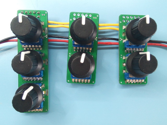 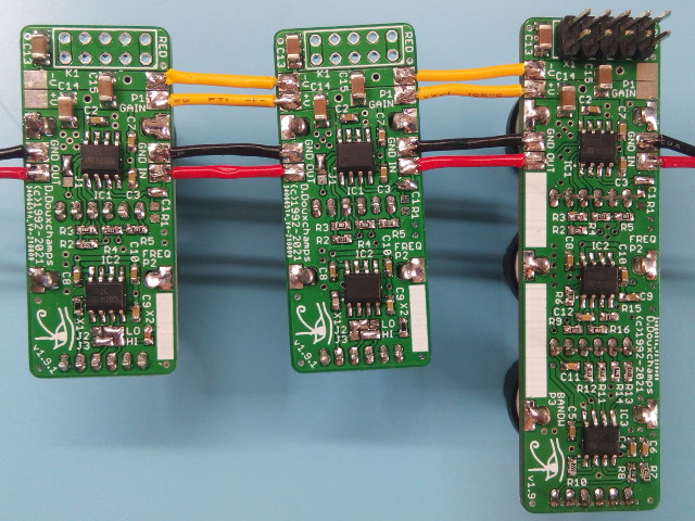 SchematicThe schematics for the parametric and the baxandall/shelf stages are respectively (click for a larger view) 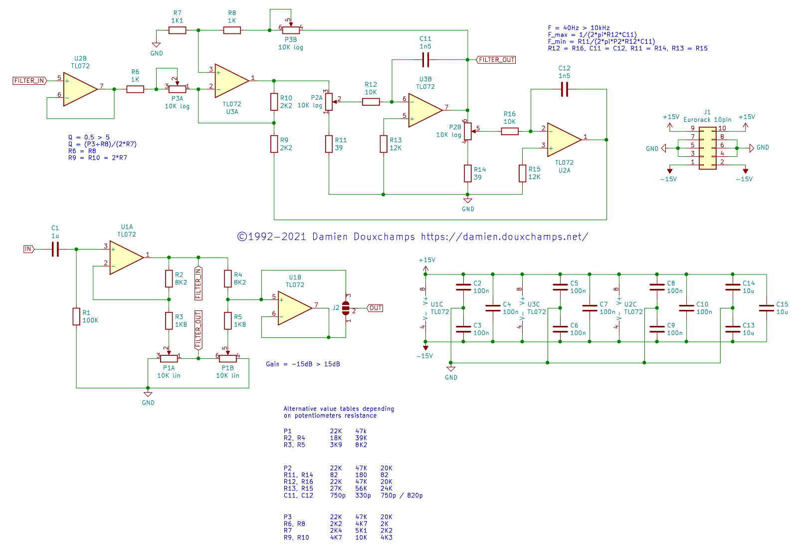 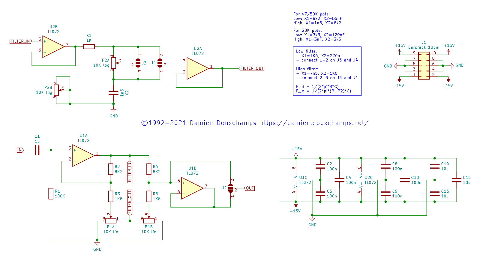 There's a few things worth noting about the schematics:
For those who want to do some simulations, Mike Stricker sent me the SPICE model of the parametric equalizer circuit. If you wish you can recalculate the values of some resistors/capacitors to obtain different frequency ranges for each parametric filter in the cascade, akin to an 'advanced graphic equalizer'. Some models of commercial parametric equalizers use this, but the default in my design is to use the same full-range for each filter. If you want to go down that road the formulas are in the schematic. Regarding the power supply: the circuit requires symmetric power rails (+V and -V). You can simply choose the supply voltage depending on which op-amp you selected. For the TL082 the power rails are typically +/- 15VDC. However given typical audio signal levels of +/- 1VAC the circuit should still run fine on +/- 5VDC (slew-rate caveats apply). For the Eurorack fanboys, +/- 12VDC is fine :) PCBAs advertised before, the PCB is very compact: 19x66mm. It can fit comfortably in a 1U 19" rack (horizontally) or in 2U (vertically). PCB interconnection is straightforward: the connections for power and signal are aligned when you place the filters of your cascade next to each other, hence very short wires or jumpers will suffice. Note that the PCB width of 19mm is slightly smaller than the knob pitch of 20mm; this is to allow for manufacturing tolerances (both PCB and front panel). The design will fit in a Eurorack module (which just to be clear is quite different from a 19" rack) but it is not ideal yet as it doesn't fully utilize 4U height. Note also that audio I/O ports are not on the board, thus you can use any connector you want, from XLR to 2.5mm jacks. Having switched to Kicad for PCB design means I can now provide 3D renderings of the boards. Can... not... resist: 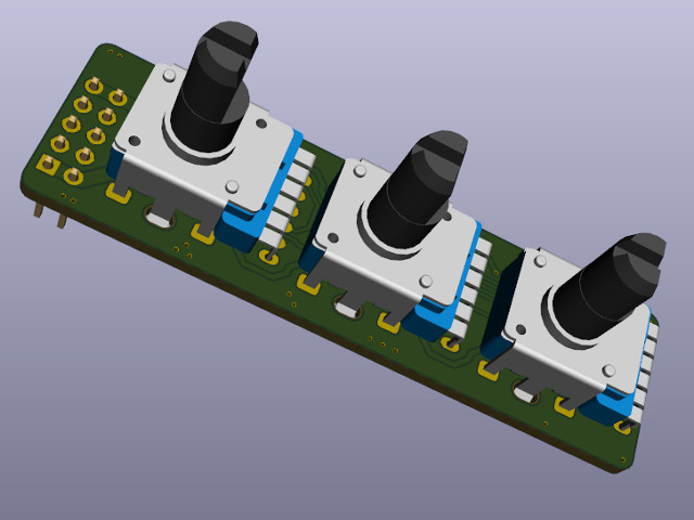 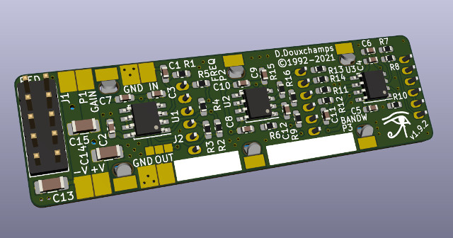 For those who want to give this circuit a try the BOM will certainly help. I am also running small batches of PCBs when there is demand. Current prices for the raw/unpopulated PCBs are:
To this you have to add shipping, typically 15-30 euros. Payment can be done by bank transfer (free for most European countries) or PayPal. Current stock: 22 parametric PCBs and 25 shelf PCBs. Contact me if you're interested! | |
| © 2024 Damien Douxchamps. All rights reserved. | |

