Aladin interfaces | |
|
On these pages I will present a little information about interfaces for the dive computer 'Aladin' from Uwatec (now part of Scubapro). A lot of the material is about 15 years old but I recently (2013) made a new version that prompted a massive cleanup of this section of my website. Most of the stuff was irrelevant since recent dive computers have a much larger memory, making antiques like the MemoMouse obsolete. But there may be a few old-skool divers with an Aladin on their wrist. After all, if it works, don't fix it! SchematicTwo classic schematics exist: one for download only and that can also set some parameters of the Aladin. The latter has some issues and since it never actually worked for me I am going to skip it entirely. The original schematic, whose source I have forgotten, uses a uA741:  I used this interface for many years, but the major problem is that recent PCs don't have RS232 ports anymore. In order to have this working one would have to use a RS232-USB converter, which in theory would work. Except it doesn't, reliably at least. The curlpit lies in supply rails: your off-the-shelf USB-RS232 converter may not give you a clean +/12V. Instead, you'll be lucky to even get a negative voltage rail. The result is that the above circuit works can upload your profiles to your PC about 10% of the time. Ouch. To fix this we first use an LM358 instead of a uA741. Next we use an old suggestion Steffen Klupsch: replace the 1N4148 diode with an LED. This has two advantages. First, the threshold voltage of the comparator can be set to about 1.5V by setting the current in the LED with its series resistor. The current/voltage curve depends on the LED; I used 3K for my LED but YMMV. Next, the LED provides a nice way to tell if your circuit is powered. This may look trivial, but RS232/USB converters or (recent) RS232 interfaces don't actually set the DTR line high before data is sent. Thus you may have to send a couple of characters on the interface to 'hot-wire' your interface before launching your dive log software. My datasheet for the LM358 clearly says that you should be careful not to apply an inverse supply to the chip, otherwise it can be "permanently damaged". To prevent this a diode is placed on the positive supply rail stolen from the DTR line. In the end we obtain the following schematic: 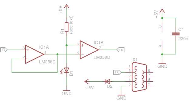 I am using WLog for my dive log and it works very well with this circuit (while, again, the uA741-base schematic fails miserably). Those who prefer to use the original software can get DataTrak (for DOS) here. As mentioned above, depending on your OS/computer/interface/etc you may have to wake your RS232 port up before starting your dive log program. I'm running Linux so before launching WLog (in Wine) I simply execute echo AA > /dev/ttyUSB0 and the LED lights up showing the interface is ready. PCBI have been using SMD exclusively for about 10 years now so the PCB I propose here is rather compact. It can fit within a DSUB-9 shell easily. Remember to keep the wires between the Aladin and the PCB very short (10cm max) to avoid excessive capacitance. 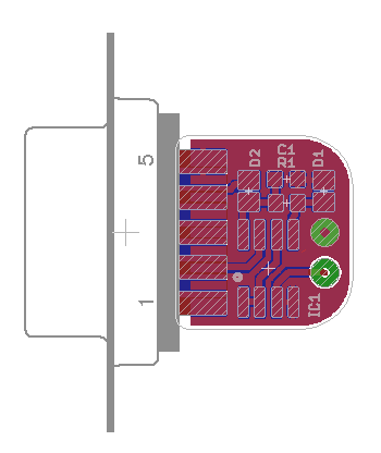 Here's some pictures of the dirty prototype. Note the "flying" diode; I had just discovered it was a good idea to add it :-) 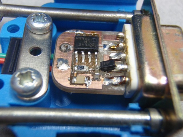 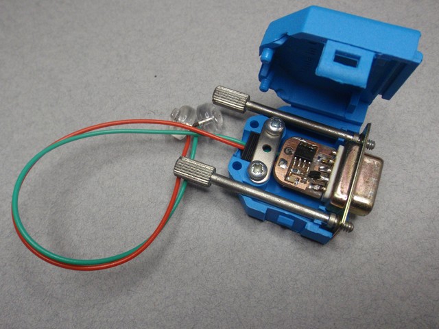 Other schematicsThe classic bi-directional interface comes from Christoph Korber and was widely spread by Matthias Heinrichs. It has a few problems that I discuss in a separate page.  Another interesting idea from Pierre Brial: simply use a hex inverter chip! This works without external components, and could even be reduved to a dual inverter in a SOT23-6 package for example, making this the smallest aladin interface ever! 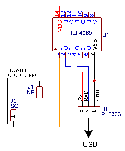 Protocol informationA couple of documents describing the transfer protocol of the Aladin can be found here, here, here, and here. From an electrical point of view, the data transfer follows this pattern:
This behavior is illustrated on the figure below. Note that when you enter the divelog mode, the Aladin holds for a short time: that is when the info is sent. Finally, the impedance of the Aladin port is about 1M when it drives the line, which explains why short wires are essential.  EpilogueA little family reunion... 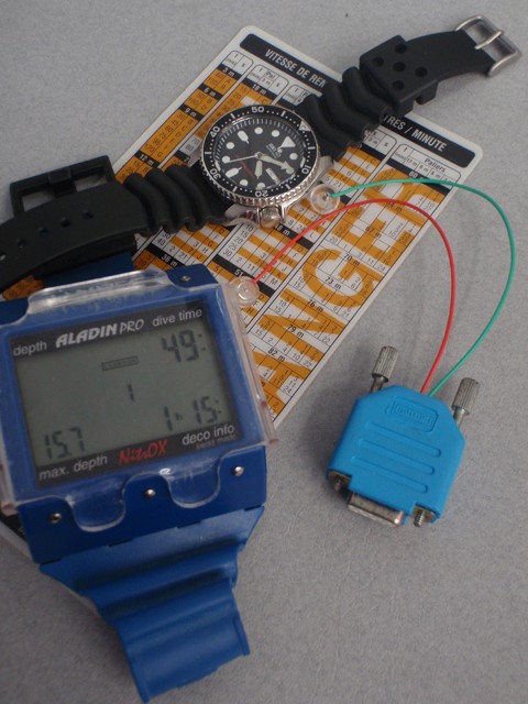 | |
| © 2024 Damien Douxchamps. All rights reserved. | |

