HP6632A silent fan control | |
|
The Hewlett-Packard HP-6632A and its siblings are great power supplies that can literally be obtained for a song. As long as the rate for a song is around $20, which I think is the case today :) I've checked the market recaps! Seriously though, these power supplies are awesome not only because they are good and cheap but also because they can sink current and thus serve as a poor man's electronic load. More better! But they do have one hell of a problem: they are loud. That makes them almost completely useless in a lab environment. There's a few videos and howtos on the interwebs about possible solutions, but none are great. One guy used a temperature-controlled fan, but since our fan here is a pusher it always have cold air flowing through it and that won't end well. Another person used PWM-control with an arduino. Overkill, I say! The 6632A already has a nice darlington transistor (TIP-122) and all we need to do it to use a simple voltage control to adjust the fan speed. Here's the idea: 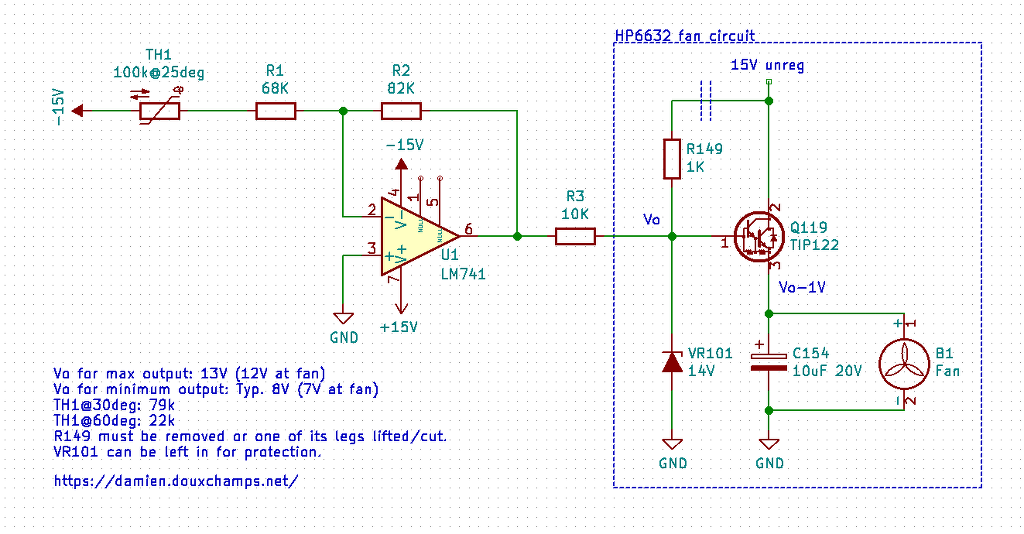 Schematic of a temperature control for the HP6632a. Yes, that's it: you only need 5 components, no special PWM fan and no software to make it happen! The section in the blue box on the right is what is present in an unmodified HP6632A. All we have to do is remove the constant zener-based voltage regulation made with VR101 and R149 by something smarter. By the way, the 14V zener means there will be 13V fed to the fan, which is a 12V rated device. So not only is the 6632a loud but it's also overdriving the fan for more extra loudness. Boooo... So here's how we fix this. An NTC thermistor is used as sensor. I used this one. Its resistance is 100K at 25deg, 79k at 30deg and 22k at 60deg. I chose to have minimum RPM and noise at 30C and want the fan to go full blast (but not overdriving itself!) at 60 degrees. The fan is practically inaudible but still rotating fine with a 7V supply, which means we want the voltage swing at the base of Q119 to be between 8V and 13V (the transistor B-E junction drops about 1V). So let's get our basic op-amp formulas. We find two relations for the two unknowns, R1 and R2: 13V = - R2 / (22k + R1) * Vin 8V = - R2 / (79k + R1) * Vin From there we plug Vin = -15V and simplify/combine the equations to find R2 = 79K and R1 = 68K. 79K is not a standard value but 82K is close enough and will do. And... Well, to be honest, that's about all there is to it. Now on to building this little circuit... By the way note that you can use a uA741 for this job, which is a good opportunity to finally use this old stock of 100 op-amps you bought 20 years ago. 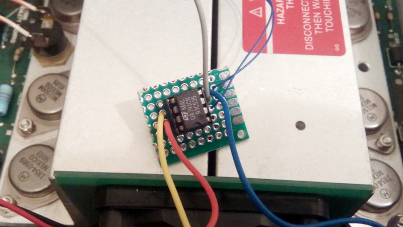 Yes that's all you need! A simple DIP-8 op-amp and, admittedly, three SMD resistors on the solder side. Making a small prototype PCB is definitely left as exercise for the reader. The practicalities of integrating this circuit in the power supply are more interesting... First and foremost one must find a suitable place to put the NTC thermistor. Even with wires and heat-shrink tubing installed, the thing is tiny and should fit in any hole we can find. I used one tube over one pin, then one tuber over both pins (thus no tube over the second pin only) to keep it as think as possible. Be careful to properly insulate the wires near the thermistor blob itself. 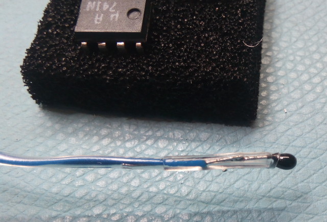 The tiny NTC thermistor we use for this project, compete with wire soldered and heat-shrink tubing applied. As luck would have it, there is a tiny hole that can be used in the heat sink, right at the end of it near the case exit holes: 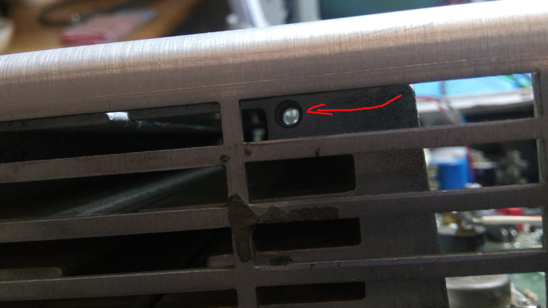 A well placed and well sized hole for our thermistor. You will note that light does shine through the hole, but it doesn't go through the heat sink all the way. Instead there is a small vertical hole on top of the heat sink. This will be useful later to see the bulb of the thermistor and seal it with glue: 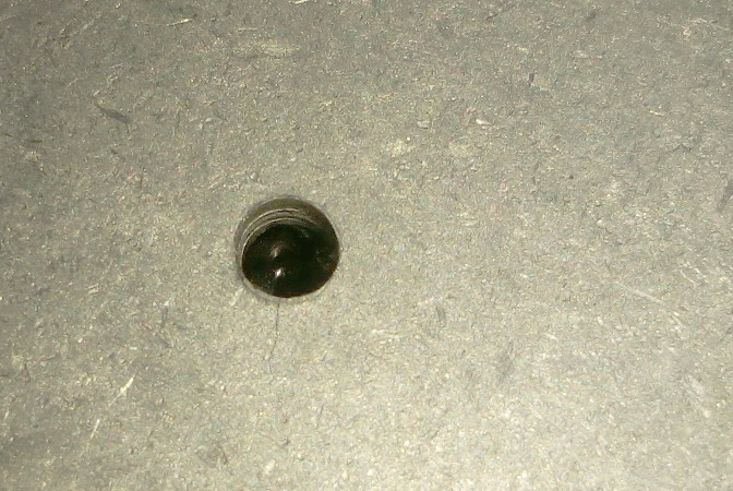 Another well placed hole. You may be able to see the shiny bead of the thermistor in it. Now we can connect and mount the PCB. I used an adhesive cable-tie anchor on the body of the fan. Together with a small cable tie and small notches on the PCB we can quickly affix the PCB securely. The connections to the PCB (which you should do before attaching the PCB of course!) are limited to 3 power wires and the 2 thin cables of the thermistor. The 3 power lines can be hooked on nearby capacitors C155 and C156, noice! The output of the circuit if fed through a 10K resistor to the base of Q119. You can attach the wire to R149, and don't forget to cut the leg of that resistor that is connected to the 15V unregulated supply! (You can remove that resistor altogether and connect the wire to VR101 too.) 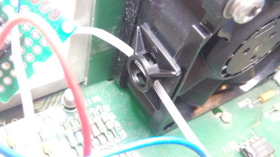 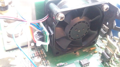 Attaching the PCB with a cable-tie anchor. Everything can be solved with either (1) duct tape or (2) cable ties. For the thermistor cable I used (again!) a cable tie anchor but with some notches made to slip the cable in. I totally didn't forget to slip it in before soldering it. But in the end this solution with notches means it's easier to disassemble so I'm happy with it. 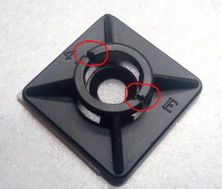 Two notches in the cable tie anchor Once the notches are made the cable can be slipped in and once the mount is rotated the cable won't be able to escape: 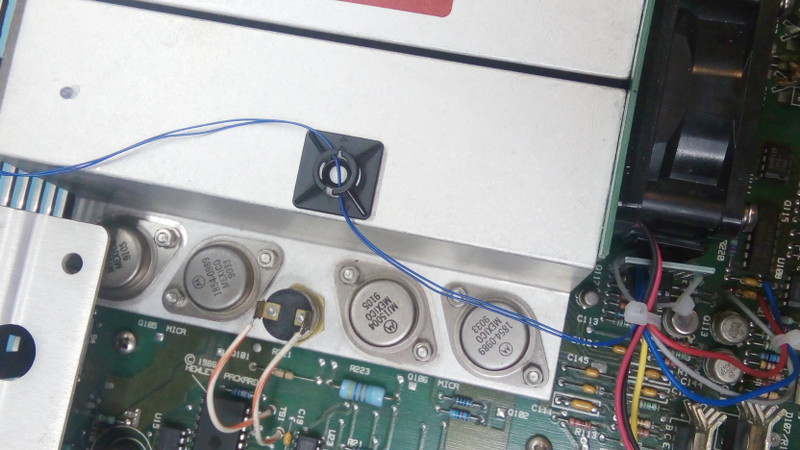 The cable-tie anchor acting as cable anchor for the thermistor wires. Note how the S-shape of the cable path interlocks with the black plastic. The last bit is to pour some glue in the top hole of the heat sink, right where the thermistor bead resides. 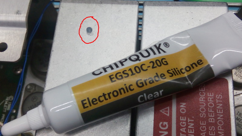 A drop of glue in the thermistor hole I used some silicone adhesive I had on hand, other ones may be more appropriate. Rigid ones like cyanoacrylate may not be appropriate though, since those make a hard rigid bond that may break with thermal expansion/contraction of the heat sink. And that's it! The power supply is now completely silent. As final test I used a hot air gun to warm the heat sink up and sure enough the fan started to spin faster. It also quickly spun down, indicating good cooling. Last note: if you're afraid this could toast your PSU don't be. First those are dirt cheap (ok that's not a good excuse!) and second the heat sink is equipped with a thermal switch. Thus if somehow your circuit fails the PSU is protected. Great success! (A few months after doing this hack I stumbled upon this similar mod which uses a TL431 instead of an op-amp. While I prefer my sensor placement I have to admit the TLP431 is a more elegant solution, requiring less changes to the PSU and also not requiring extra 15V rails.) | |
| © 2024 Damien Douxchamps. All rights reserved. | |

