HP-66311B Mobile communications DC source | |
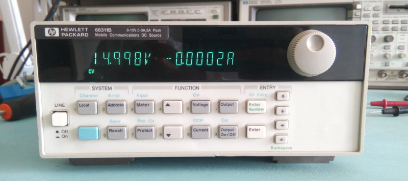 The HP-66311B Mobile communications DC source The HP66311B is not a very common instrument and its name makes it often pass under the radar on auction sites. The lack of front binding posts is also not very practical and enticing for the hobbyist. And that means... an opportunity! The first boot of this instrument being successful is a good step but let's also have a look at the self test and error lists: 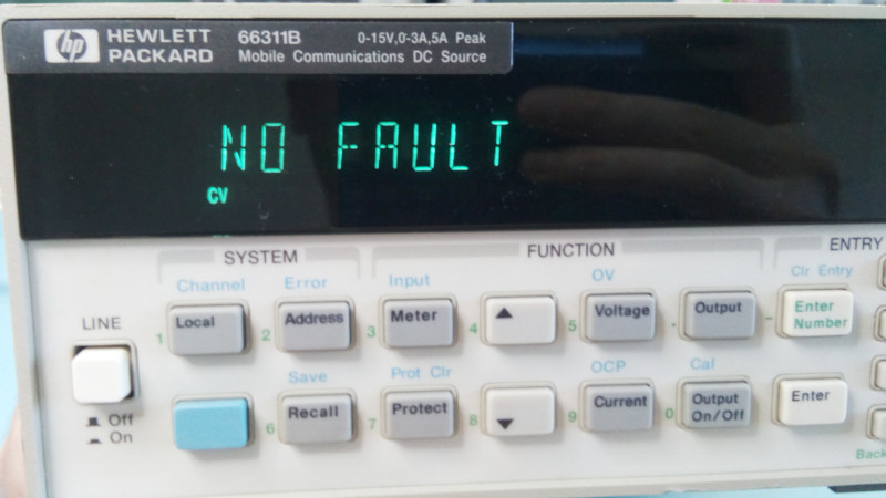 Successful self test: no faults! 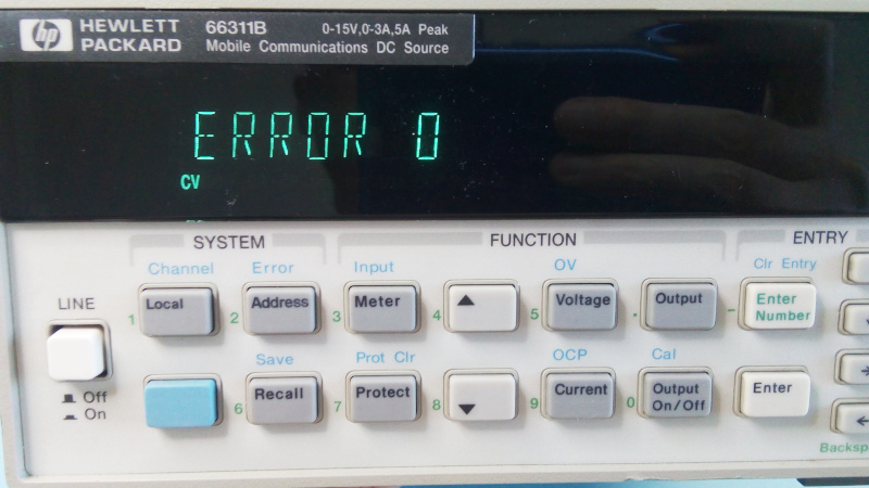 'Error 0' means no errors, also very good! All looks good, seems like a score! Of course the most important is not to turn it on but to take it apaaaart :-) The case is based on the classic design of the 34401A multimeter but with the handle holes blanked. That makes total sense given that this little instrument weights as much as a minor planet (more than 9kg!). And we'll soon discover why. In fact opening the 66311B we immediately feel that something is a little odd in the force: the outer shell is heavy. I mean, seriously heavy. Let's get the scale and weight this war-ready shell: 2.4kg! For just the shell! Auuugh! Even power supplies that push more than double the wattage don't have such heavy shell! A quick check with the caliper shows that the steel of the shell is 1.5mm thick. Daaaamn. Was someone paid by the kg at HP during this instrument's design? I'd love to know why this was necessary... Here's a little pic of the steel thickness: 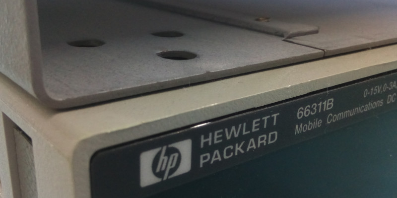 1.5mm is a little bit more than required, methinks... Now let's look at the gory details of the innards... Well there's not much to mention really. The whole thing looks a bit like a diminutive (and yet more sophisticated) HP-6632A: 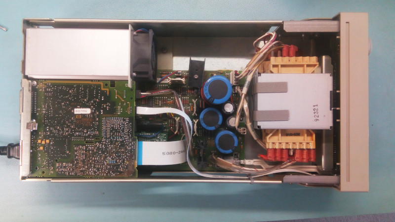 Inside the HP-663111B The first thing I notice is the dusty fan: this unit had a long and productive life... The fan is also very loud, but this seems to be a regular complain about this device. We'll fix that later. 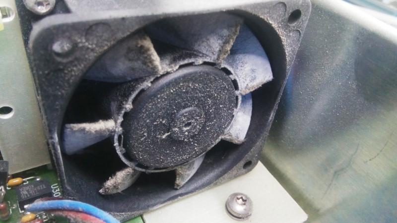 Dusty fan = long productive life. And some expense ahead... Some bodge resistors are already visible. BTW this unit is the older "through hole" PCB version. A later release has an SMD board. 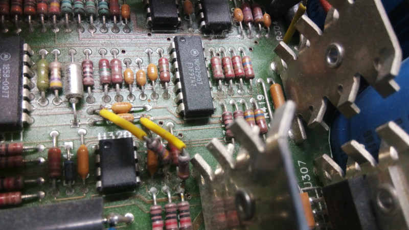 Just inside and bodge resistors are already right in front of us! To see more of the main PCB we need to remove the CPU/logic board. This requires unscrewing the RS232 and HPIB connectors from the back panel. After that a bit of juggling must be performed to liberate the PCB: 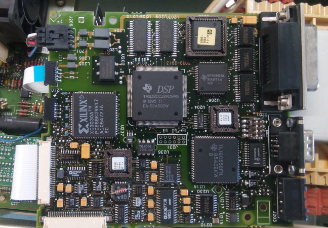 The small logic board for this power supply It's a little surprise to see a Texas Instrument DSP (TMS320C32PCM40). The Xilinx chip is not an FPGA but an older CPLD. Eagle-eyed ones among you will have noticed... yet another resistor bodge! 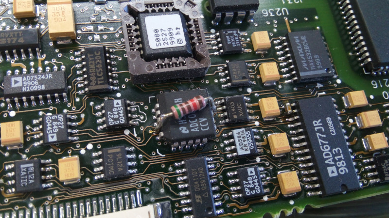 Cute pink resistor bodge With the logic board out of the way we can see the entire analog board. It does have a large daughter board on it but I haven't pushed the disassembly further. You will note on the pic below that the input filter in the lower left corner does not have RIFA caps, noice! 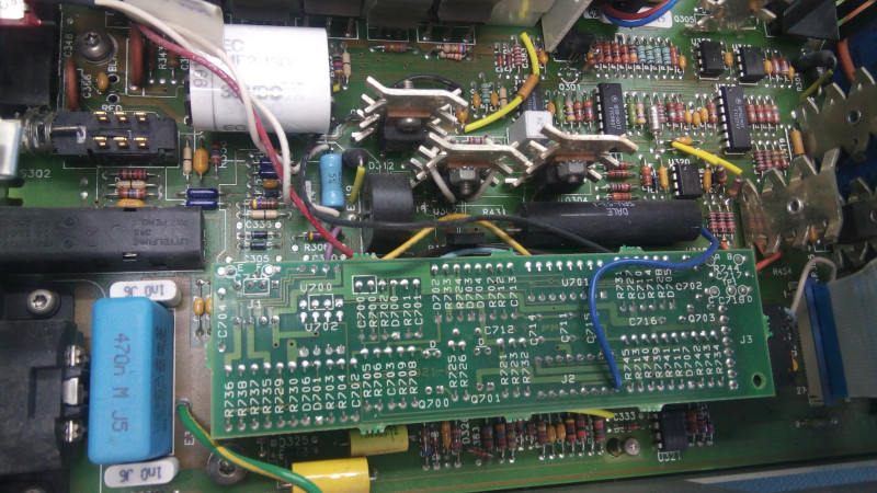 The part of the analog board that was hidden under the logic board. We can note yet another resistor bodge on analog board: is this the theme of this instrument? :D 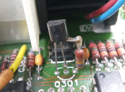 More bodge resistors... Another little interesting detail: the large electrolytic capacitors are not held together by cable ties or glue/silastic but instead HP used a nice rubber band. One point for originality! 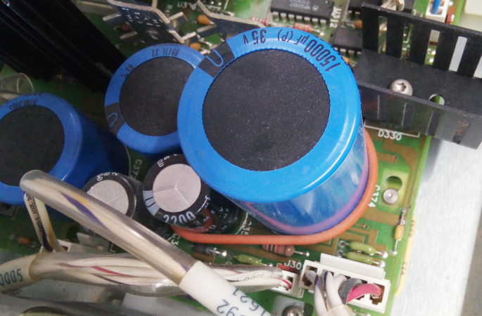 A rubber band holding the capacitors together for vibration compliance Since the fan is quite noisy and seems to be (so far) the only part that needs replacing I guess it's time to remove it and find its model and specs. The assembly is quite similar to the HP-6632A: the fan is screwed to the heat sink with a blank PCB sandwiched in between. The fan mode is PAPST type 612 (only the best for HP!). It's a classic 12V jobbie of 25cfm but with a horrendous 40dBA for its noise specs (when it was new, it's a lot worse now). I'll replace it in another article soon. 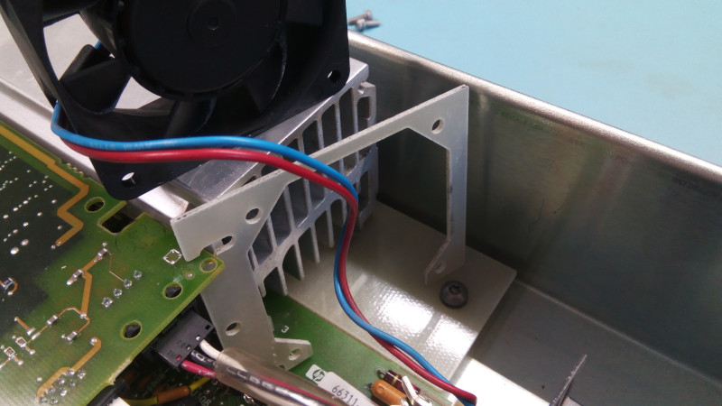 The fan assembly with the sandwiched PCB 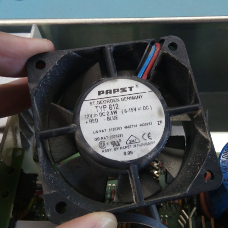 Dirty old fan, but top notch quality with Papst! A couple of things before reassembly. First there's a couple of strips on the transformer, trim strips! Yes, like the ones found on the outside of HP instruments (specifically for covering rack handle mounts). Then you can see that the front panel has a couple of holes that are used for other PSU models (or maybe the HP33120A generator). Those will come handy if/when I add front binding posts. They are hidden by the front panel 'veneer' and the latter is quite thin, leading to many devices having dings and punctures at those locations. There's a large interesting thread about this instrument on the EEVBlog forum, worth a look! 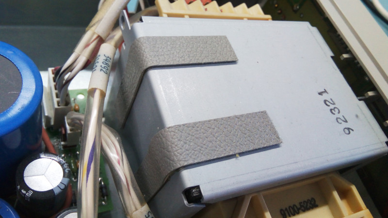 Trim strips inside?? 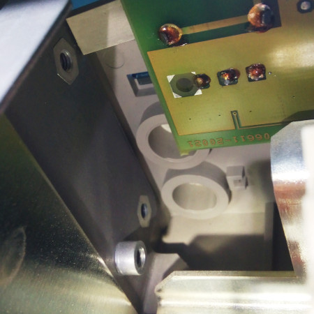 Two panel mounting holes are available behind the front panel veneer Now we can close this baby and run some basic tests: open-circuit voltage and close-circuit current: 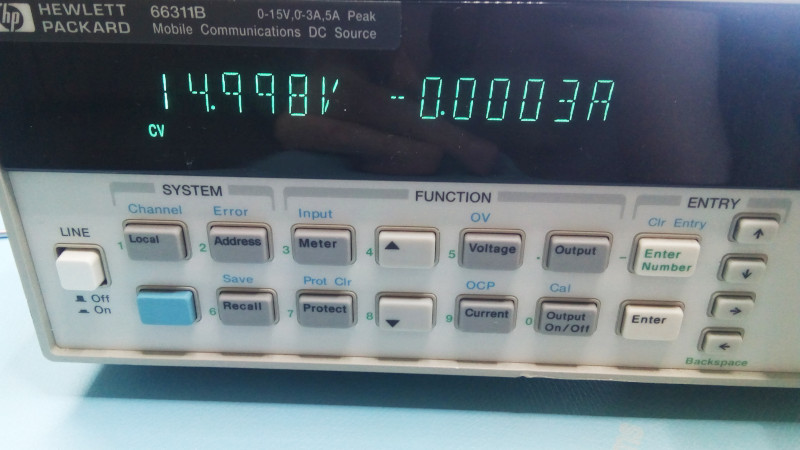 15V output set on the DC source 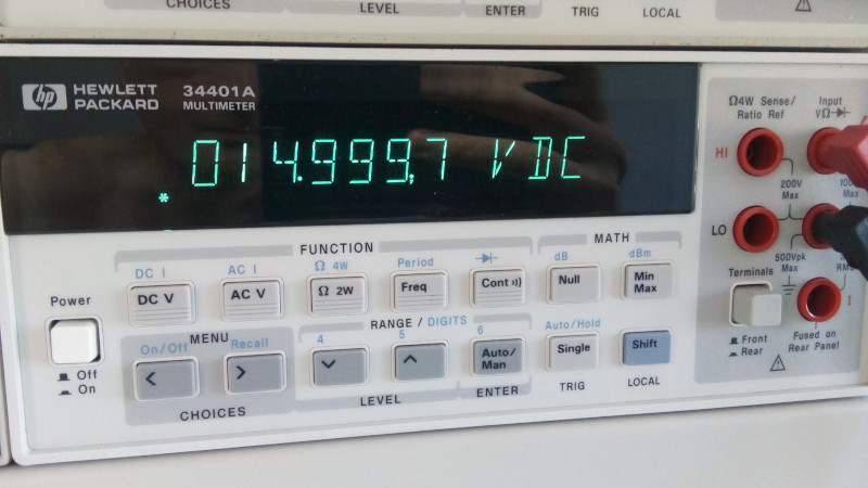 15V measured with an HP-34401A 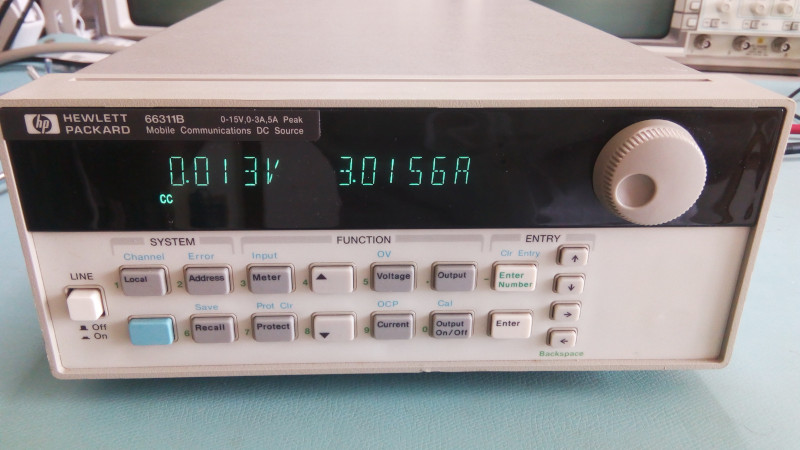 Short-circuit output of 3A These results look pretty good to me! The 3A current is a little off but it's in short circuit mode where the output voltage is really low so I won't bee to hard on the poor instrument. Of course full power tests are needed too but I'm still looking for a good DC load... | |
| © 2024 Damien Douxchamps. All rights reserved. | |

