HP-54600B Oscilloscope repair | |
|
I bought yet another non-functioning instrument at an auction: a venerable HP 34600B. Venerable because that's the scope that had just been installed in the labs when I was at the university. And also because I was eyeing those as a teenager. 'Nuf said, sentimental Hewlett-Packard stuff. This scope model has two well known issues: a vertically shrunk image, which is solved by replacing some caps in the CRT high voltage section, and a cracked front panel PCB. My purchase was suffering from the latter. What happens is that the front potentiometers are attached to the front panel PCB, not the sturdier front panel itself. Combined with a thinner than usual PCB, this is a time-bomb as whenever a potentiometer knob is pushed a bit the inner PCB will flex. Oh and this also happens for the soft keys. In other words, the PCB takes the brunt of the interaction stresses, and over time it ends up developing hairline cracks, which obviously grow until a real crack appears and breaks the PCB in many tiny bits. The auction description mentioned the time base 'potentiometer' (those are actually rotary encoders) which was not working, hence there was no way of changing the time base except with a press of the auto-scale button. Nicht gut! Upon closer inspection after receiving the unit, I found out that the horizontal 'delay' (scroll) knob was also not working. That was interesting because it meant that it wasn't the time base encoder itself that was NFG but rather something common to both time base adjustments. Which is scary as it can point to real hard and complex circuitry! But there was another hint: although the controls did not work, they did provide some input: they were both able to change the horizontal settings but only within a +/- 1 setting range. In addition, this was happening in an alternating fashion with the changes being like this: +X, 0, -X, 0, +X, ... IOW every other 'click' of the encoder was doing nothing, and the other two were successively canceling each other. 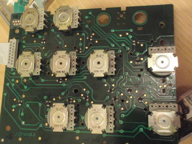 The front panel board, already with some annotations. After further analyzing the encoders themselves I found out that they are quadrature encoders. Those have 2 outputs for 2 bits representing 4 quadrants. 4 quadrants allows the direction of the rotation to be known: if you were at position 2 and are now at position 3, you increased by 1 (for example, turning the encoder clockwise). Now it made sense: if one of the two lines for an encoder is disconnected, then the scope will see the encoder going e.g. from position 2 to position 4 (with a non-change position in the middle), and then from position 4 to position 2. Hence the back and forth and the every-other-position change. 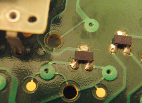 The little dual-diodes in SOT-23 were not the issue... The front panel of the scope mixes about 17 switches and 10 encoders and is not trivial to analyze. I spent some time trying to reverse engineer it, and at some point realized that although the encoders were indeed working properly, they had no effect on pins of the front panel connector that should have changed. Thus the problem was in what lies between the encoders and the front panel connector: the PCB or the multitude of small diodes found on it. After testing all the diodes the last suspect was the PCB. The classic problem! 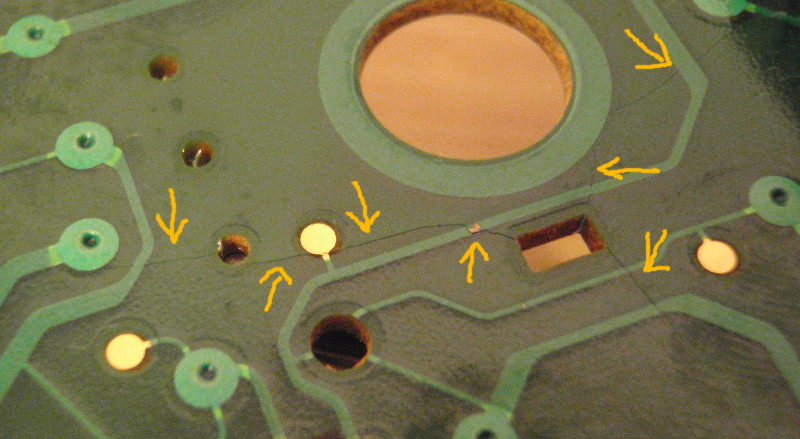 The cracks! Up to this point I had of course not noticed any cracks on the PCB, which I had inspected before knowing about that common issue. But every clue pointed at the PCB, hence I gave it another look. Nothing wrong. WTF? Then I gave it a real other look: 10x loupe, strong lighting. Nothing. Gaaa! I used the continuity meter to go along the relevant PCB traces, and clearly two of them were cut! But no cracks anywhere to be seen. On my third inspection though, I finally noticed it: an extremely fine hairline crack, about 2 centimeters long, had cut a trace! The (potato-vision) pictures show the cracks quite well, but you really need to tip your tongue at the right angle and have the right lighting to see them. They were practically invisible. 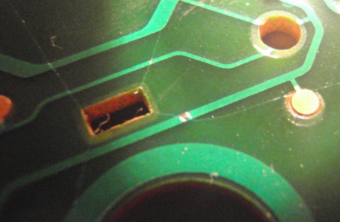 More cracks: notice the 4 cracks leaving from the 4 corners of the little rectangular holes. Rectangular holes are bad kids, don't follow HP's example here! Removing one the horizontal scrolling encoder was necessary to access the trace for repair. Easy peasy. But then with the encoder gone I had a better view of the area and a few more hairline cracks could be seen. Argh. Luckily they were present only on the back side of the PCB (the side with the encoders), which is logical given the direction of the strain the PCB is subject to. 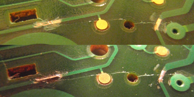 Two traces with their resist layer removed. Below, the repaired tracks. In the end 4 or 5 track repairs were needed. Those were done the usual way: scrape the green resist layer with a box cutter, then solder a bridge over the cut. The cut being extremely fine bridging was very easy. After reinstalling the encoder and testing the damn thing still didn't work: one crack had escaped my attention. Re-removal of the encoder, re-checking, re-repairing, re-soldering of the encoder, re-testing... and it worked! 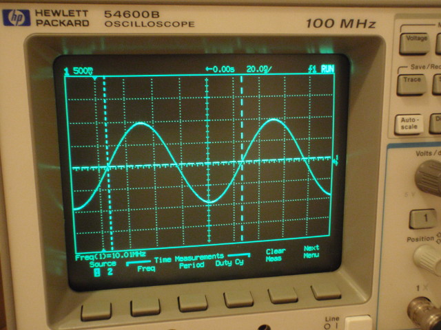 It works! The next step was to stop the cracks from getting bigger, which they would inevitably do over time. I used two weapons for this: 1) the least viscous cyanoacrylate glue I could find (consistency was roughly that of water) and 2) 2-parts epoxy glue. The first one was used to slip into the cracks and harden there. Due to the superfine nature of the cracks I wasn't sure it would work, but in the end the glue seemed to be absorbed by the cracks. I also scraped the PCB in the areas to be glued, so as to get a good access to the glass fiber of the PCB, which was more likely to absorb the glue. 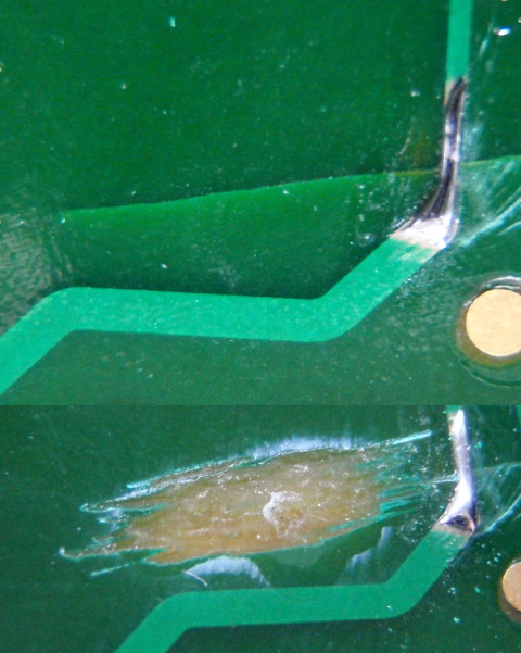 A crack, before and after scraping the resist layer off and impregnating with superglue. Not pretty but effective. The epoxy glue was used to strengthen the PCB here and there, adding thickness and rigidity where possible. 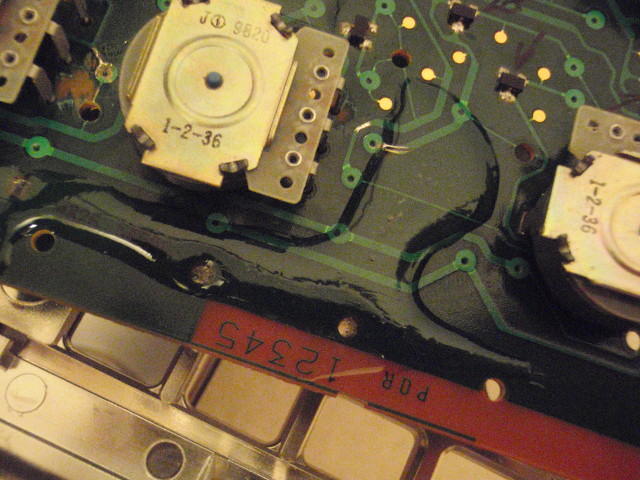 A little too generous pour of epoxy or two to strengthen the PCB. The entire repair took about four hours, but now I finally have the scope of my childhood dreams :) Of course with the years this scope is not exactly top notch any more: a good case of "don't meet your heroes"... For the EEVBlog fans, this is pretty much the same keyboard issue that Dave had: clearly that HP design has its flaws... After testing the scope showed issues with the DC offset on both channels. This could be up to 300mV so it was significant and disturbing: could the front-end be damaged? Sounds unlikely... The nice thing about these scopes is that they have a calibration output BNC in the back, and this can be used to auto-calibrate the device. Noice! Unlocking the calibration (there's a switch for that in the back too) gives access to the calibration menu; after that it's just a matter of following the on-screen instructions (limited to connecting the rear calibration BNC to the required channels) and waiting for the procedure to finish. This can take a few minutes, but after that the zero-level sits nicely at... zero. Great success! I didn't perform the horizontal calibration (delay between channels) because it requires a pulse generator with a rise/fall time < 1.5ns, which I don't have one "at the moment". Using a fast CMOS gate (like a hex inverter in a 14-pin package) could improve the transition time on my 3325B generator which sits around 15ns, but it doesn't seem to be necessary for this scope. | |
| © 2024 Damien Douxchamps. All rights reserved. | |

