Fixing a major failure of all analog functions (A/D, trigger,...) | |
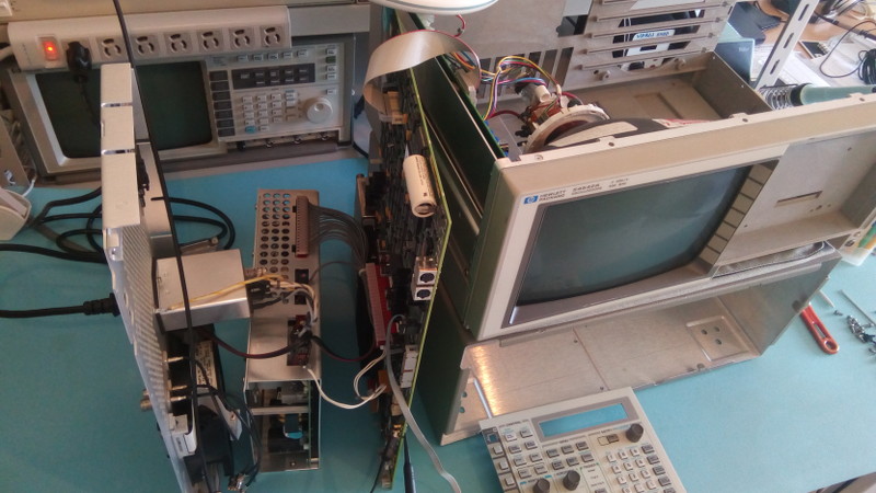 How to do live tests on your 545400 series scope I just had a nasty surprise: my HP-54542A scope just died when I was starting to investigate a fault in another instrument. Cascading failures like that can bring a workshop to a complete halt when two important pieces of gear decide to die at the same time. Auuuugh! The problem appeared as I was trying to setup the scope and could not get any normal trace to show up, not even the probe calibration signals. After 20 minutes wondering which settings I got wrong (it's a complex beast after all) I finally ran a self test. "It's kosher, it's christmas": well not sure about kosher but for sure the failures where lighting up all over the place like a christmas tree! Basically all analog functions were dead. Reverting to the default calibration did not improve anything. And there is no publicly available schematic for this scope. For sure this didn't sound very good to me. The little that's available in the service manual is not that helpful, especially when you en up on a "replace main board" action point. Ouch. One clue of what was going on was the 10MHz test signal that can be activated on the AC-CAL output in the back of the device, and which did not return a proper signal. The frequency was good, but the amplitude was wrong and the signal was stuck between 0 and -200mV. No positive, so I tried to trace why the 5V rail had failed in that section of the board. 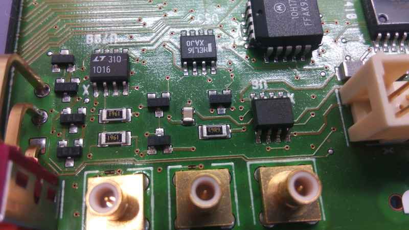 The hp54542a's calibration outputs section Of course accessing that area meant removing the main board entirely. I did this before to replace the battery but this time I would have to run tests while all the scope's innards were on the bench. And with the short PSU cables it was a bit of a challenge to find a configuration that worked (see pic above). Having had issue with tantalum caps before (oh surprise!) it's the first thing I suspected. BTW the missing +5V was 'confirmed' by checking pin 8 of U53 which should have been at +5V. It turns out this was a bad diagnostic: pin8 is at 0V and that's normal, and so is the 10MHz test signal being all negative. So I spent a lot of time checking caps and tracing a +5V signal that was actually OK. When I say 'a lot of time' I mean 10 good hours. Yikes. Oh and my handheld multimeter, which I use for measuring capacitance, turned out to also be dead! I used it 3 days ago and it was fine, what is happening in this lab??? 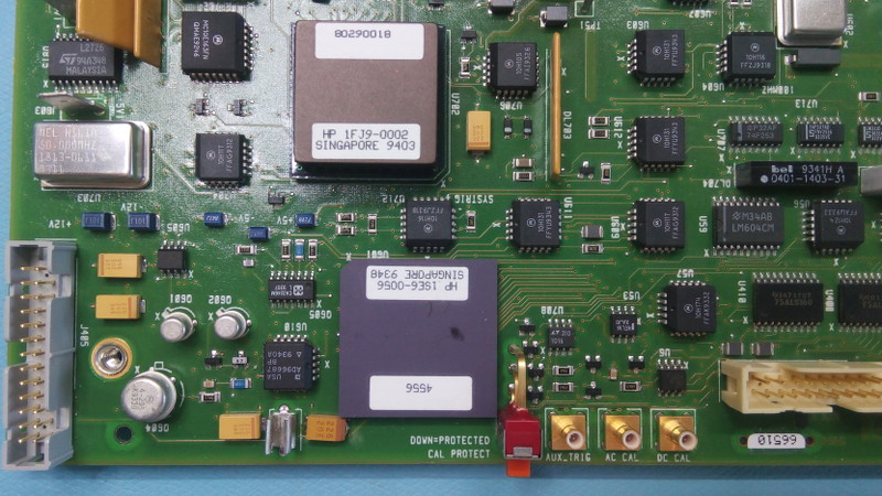 The hp54542a's calibration output and trigger sections It was a bit surreal to have the main board of a $35000 piece of gear lying on my bench, and just thinking about that made me clean the mess little. You don't want to break more things by mistake... 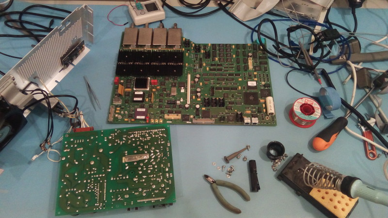 A messy workbench during diagnostic 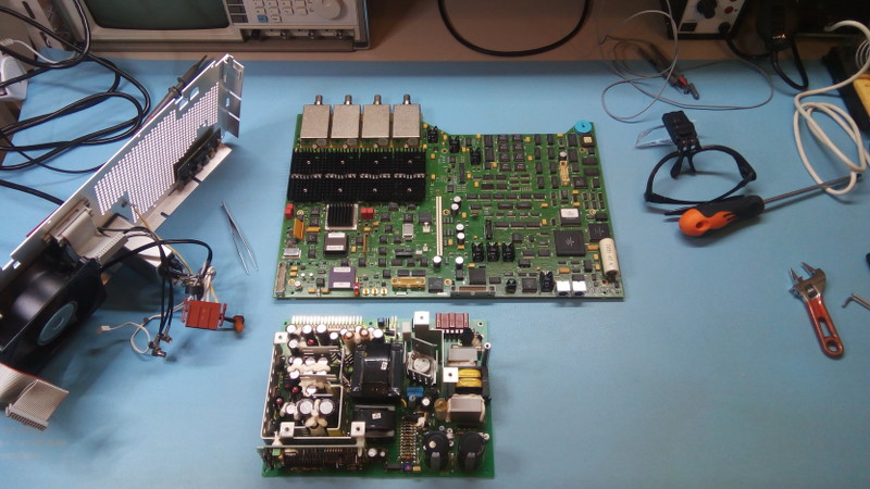 A cleaner workbench 5 minutes later After many hours I noticed that the service guide does give information about the power rails found on the power connector. A little detail that had escaped by eagle-eyed vigilance (whoaaaa). The manual asks to load the 5V rail before testing, but I don't have a 2 ohm 25W resistor in stock so I tried unloaded. Well in any case it didn't change much and one problem became clear: the -12V rail was at -4.5. A PSU problem. Doh! 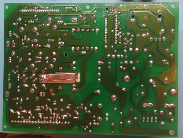 The solder side of the HP-54542a PCU board Several PSUs of HP instruments of that era are very similar, and since I have an HP-53310A I was hoping I'd be able to just swap the units and see how that worked. Unfortunately the PSUs are a little different so that was not really possible. But I did find the schematic of a similar scope PSU (54503A) that was reverse-engineered and drawn by hand by an awesome chap named Thierry Magis. Who, even more awesome, is Belgian like me. Small world. That schematic was incredibly helpful: the -12V rail is quite simple with only a handful of components. There's hope! The main piece of the rail is an LM350 regulator (A8) and it quickly became the main suspect as there was no visible damage to other components. Since the 53310A PSU contains a couple of those I replaced the LM350 with a known good one and... nothing changed! The 53310A contains exactly the same circuit for its -12V rail so comparison was possible. Unfortunately there was no clear culprit: all resistor values were good, yet the voltage at the adjustment pin of the LM350 was fluctuating like crazy instead of staying nicely put at 1.25V. WTF? I even swapped the two LM350 of the 54542a PSU and the problem remained on the -12V rail, so the LM350 was actually OK. 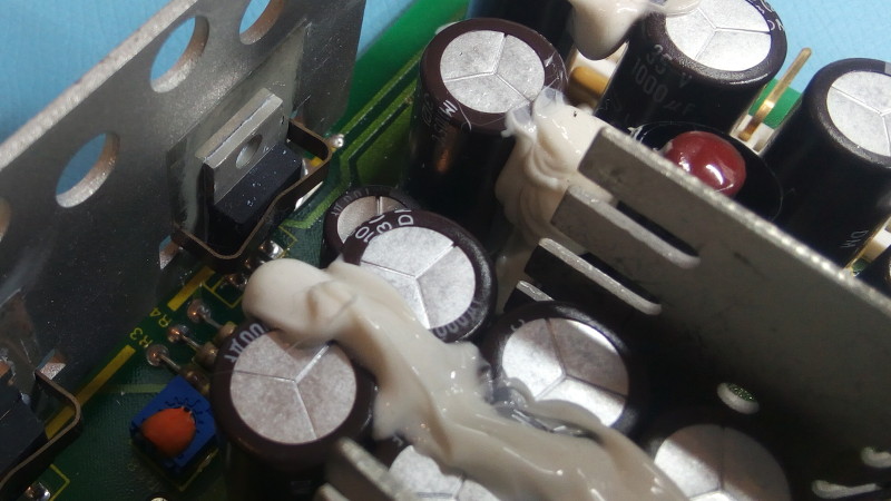 A first suspect: the -12V rail regulator (LM350) Next was to check the kind of voltage that was reaching the regulator's input. Maybe some excessive HF switching noise created an unstable regulation loop? My trusty analog scope (always good to have around!) begged to differ: the +12V and -12V rails had similar noise at their inputs, and the +12V was just fine: 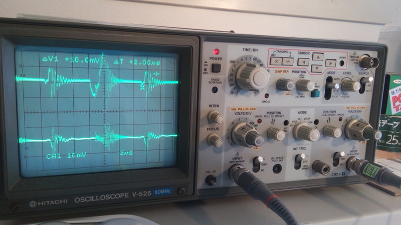 The LM350 input noise for the +12V and -12V rails I started to suspect that the components were not the issue, but maybe the PCB was. Or something else external to the components: a cut trace maybe? But nothing of the sort could be found. The voltages along the resistive divider were wrong though, so the resistors were suspect again. And after a 3rd or 4th check, they were all good (I had to remove or cut a leg to test them out of circuit). Gnnnnn! Plus the resistors are deep inside the PSU in a narrow space that is not easy to visually check. At some point, out of spite, I dragged a pointy multimeter probe between the pads of two adjacent resistors, on the components side. ... ??? WTF? It Vorks! (tm) The problem was a (nearly) invisible link between two pads! I'm not sure but this looks like dendrites to me... If so it would be the first time I experience such issue. But the scope dates from 1994, I'm not sure if lead-free solder was mainstream at the time. 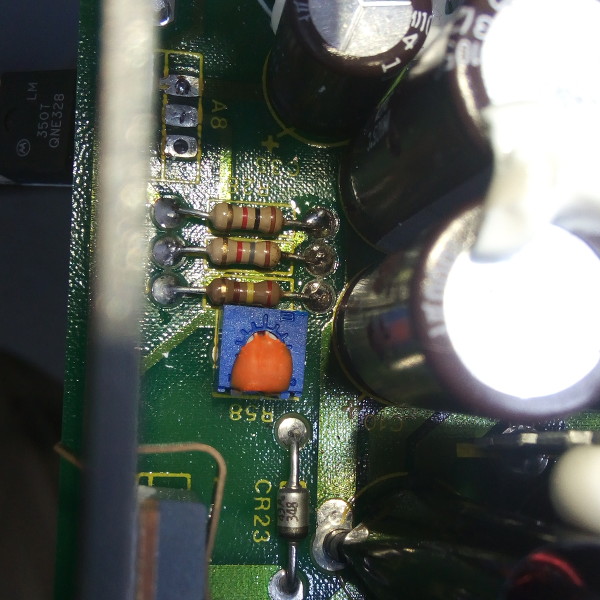 Well here's your problem! If you can spot it... The short was between the two right pads of the light beige resistors. Now for the real suspense: did the PSU brought some other components along for a ride in paradise when it died? Time for a reboot! And I was happy to see these four nice horizontal lines instead of the crazy wiggling garbage before the repair. Plus the self test was also all positive (ignore the disk drive which was absent...) 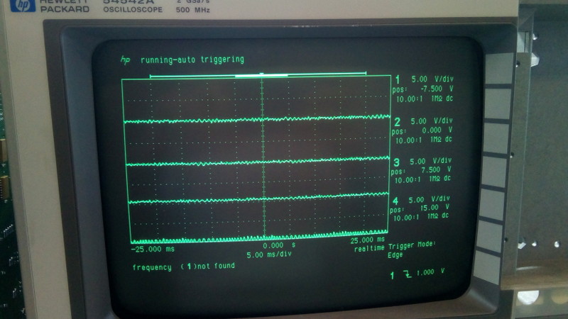 Four nice horizontal lines: me likes! 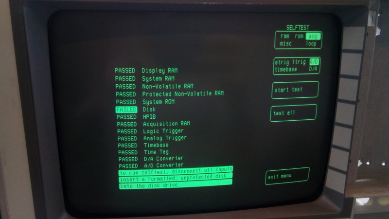 Self test: that's a bingo! Now the long task of self-calibrating can start. 40-50 minutes altogether, a drop in the ocean compared to the two days I spent on this issue... 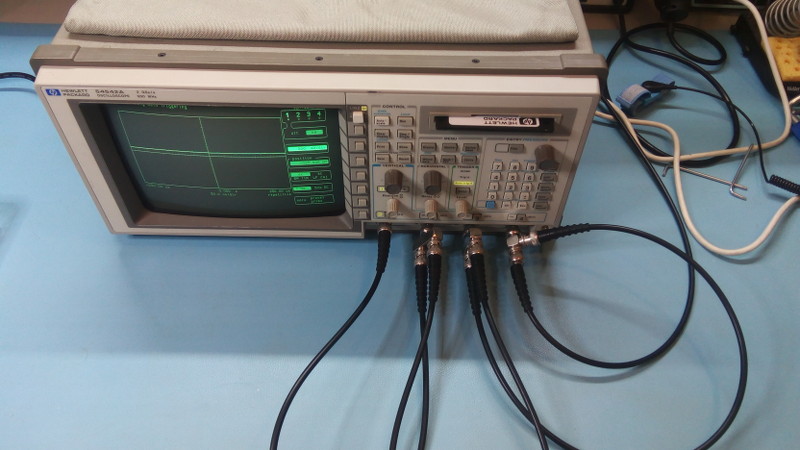 Self calibration running... 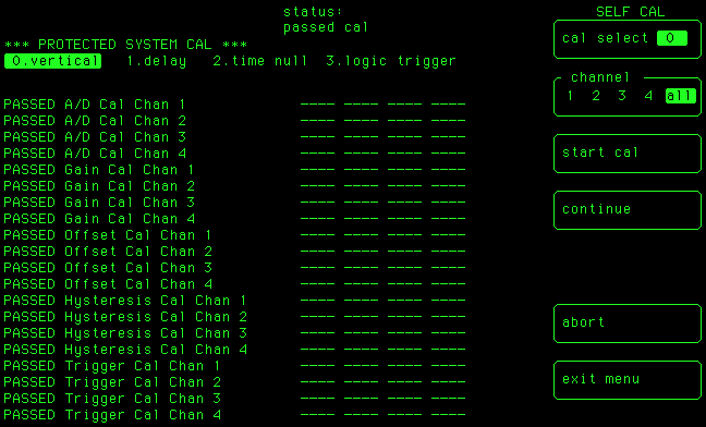 Self calibration: all vertical steps PASSED! 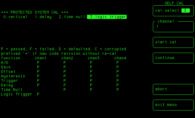 Self calibration: final results are A-OK. Great success! Now I just need to fix my handheld multimeter... It never ends... But hey! Another Hewlett-Packard device is back from the grave! UPDATE: The nice Youtube channel "Electro-Bidouilleur" has a video describing exactly the same problem regarding the same device! His conclusion: carbon buildup due to PCB aging. He took a good 10 hours to find the issue. So now I'm not too ashamed to have taken the same time myself. | |
| © 2024 Damien Douxchamps. All rights reserved. | |

