HP-3325B Synthesized Function Generator adjustments | |
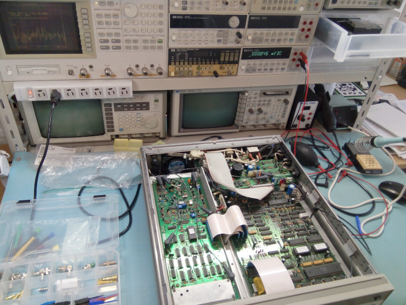 The healing bench at the start of the surgical procedure... I have performed my 3325B's adjustments before off-camera, but having recently acquired an HP-4396B I now have (almost) all the tools needed to perform an (almost) complete set of adjustments so why not document it? Let's go! First you will of course want to get your hands on the service manual, obviously. And from this manual you will want to keep page 5-7/8 (PDF page 14) at the ready: it contains the location of all adjustments and test points, plus a little picture on the left to locate assemblies/PCBs. This is particularly important because the information on the PCBs is often missing. Here's the assembly locator; I will copy the adjustments locators as needed later on. 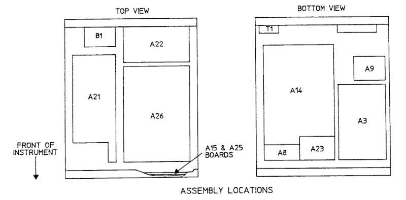 HP-3325B assemblies locator Looking at the adjustment section of the manual you will notice that it is only 8 pages long, of which two pages are for the section contents and the adjustment locator images mentioned above. So only 6 pages of actual things to do! What could possibly go wrong? ;-) Well well well... Issues start at page 1, title 1, paragraph 1. You see, there is 5-1 Introduction, 5-3 Equipment Required and 5-5 Adjustment procedures with no 5.2 or 5.4. Clearly (?) someone was not using LaTeX for their user manual. So in the end the first adjustment is 5-7: 5-7 Power SupplyThe power supply circuit is a little strange with most rails being derived from the -15V rail. This adjustment is not very critical and in fact will be further fine-tuned later. As long as the +5V, +15V and -15V rails are roughly good there would be no problem. For my 3325B I could not make all 3 rails fit in the brackets required by HP. In the end I left them at 5.148V, -14.971V and 15.050V. No worries. 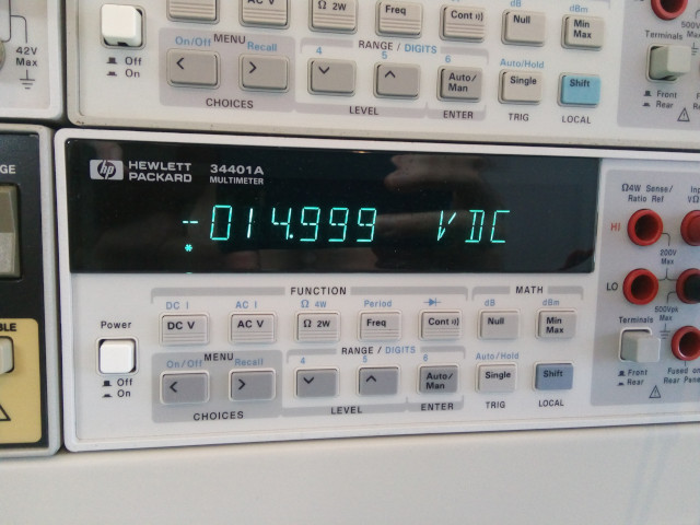 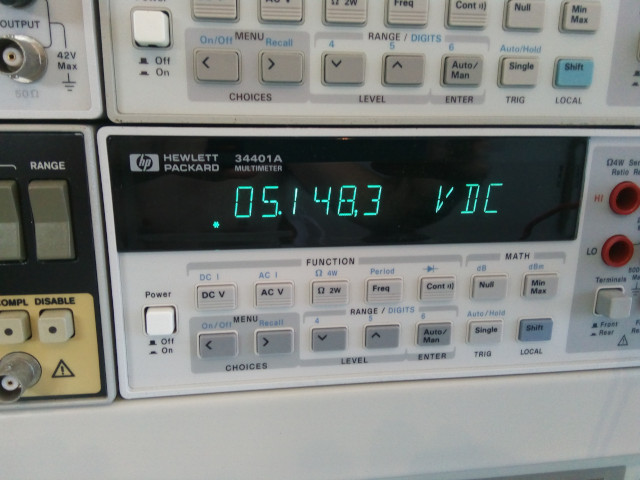 -15V and +5V rails. The 5V rail is a little off but no worries for now. It's important to look at the adustments locator because the A22 board (power supply) has +15V and -15V test points that are at -20V (-15VU, with U for unregulated!)! So you do have to pick the correct test points if you don't want to fry your brain on non-existing issues. And to make things a little bit more complicated the locator image may not fit your PCB revision exactly. Here it is anyway: 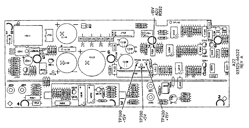 The A22 power supply board adjustment locator 5-8 D/A Converter Gain and OffsetFor this adjustment we need to set the 3325B in a special test mode using the three keys Shift, DegmVrms and SelfTest. Obviously the first reflex of anyone with PC experience will be to press the keys at the same time, like CTRL-ALT-DEL. But this is not how this instrument works, you just need to press the keys one by one. I had problems to set item (f) and found it was easier to overshoot (over 5V) and slowly bring the value down rather than increasing towards 5V. The latter was a little unstable too for me, not sure why. 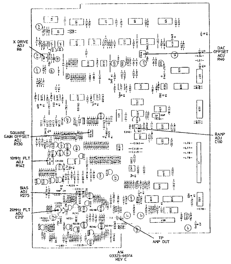 The A14 board adjustment locator 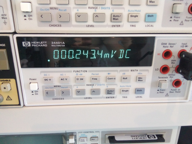 HP-3325B adjustment 5-8 (d), must be less than 5mVDC 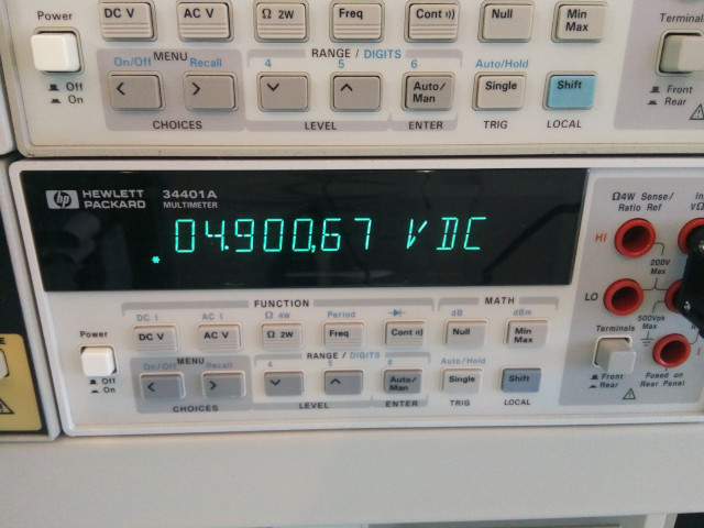 HP-3325B adjustment 5-8 (f), must be 5VDC +/- 15mV, but is clearly not 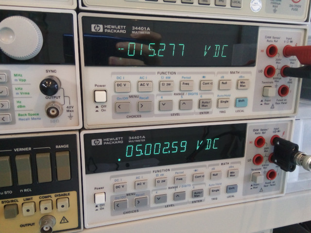 HP-3325B adjustment 5-8 (f), much better. Note that the -15V supply rail is not even further from the first adjustment recommendation, but that is OK. 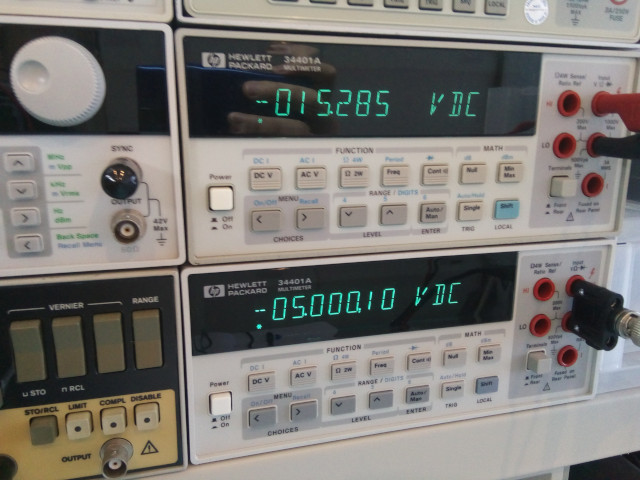 HP-3325B adjustment 5-8 (g), nicely equal to -5V. In the end the calibration values are reported well within the +20 / -20 range, noice: 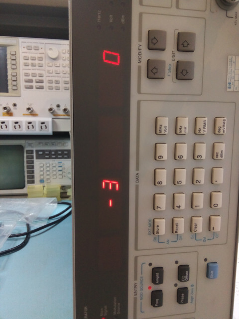 HP-3325B adjustment 5-8 final parameters, must be both within -20 - 20. 5-9 Voltage Controlled Oscillator (VCO)A simple adjustment without issues: just adjust for -3V and check that another test point is around -10.5V. 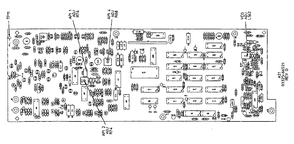 The A21 board adjustment locator 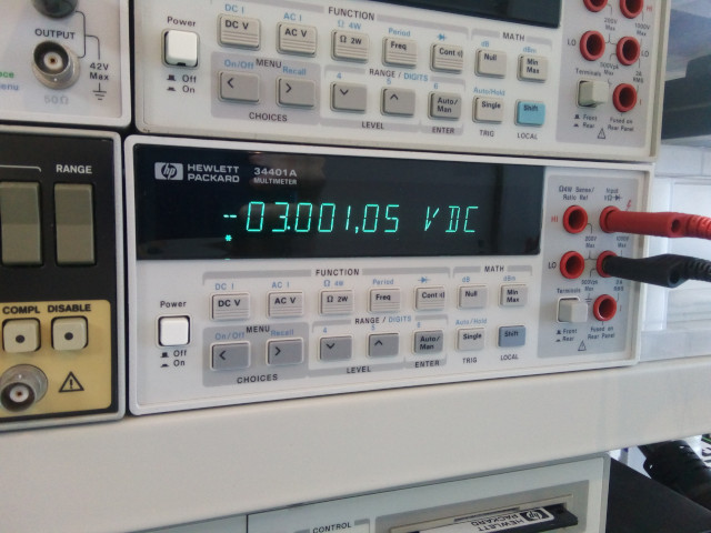 HP-3325B adjustment 5-9: must be 3V 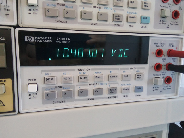 HP-3325B adjustment 5-9: must be between 9.4V and 11V 5-10 Analog Phase Interpolation (API)Finally a use case for my 4396B in this procedure! Unfortunately I could not see any API spur in the spectrum so I had to leave this setting alone. I must have made an error in the setting of the spectrum analyzer?? In any case after 3 hours of trying to get it right I moved on. Here's the kind of spectrum I would see: no spurious little peak to optimize at 3KHz... 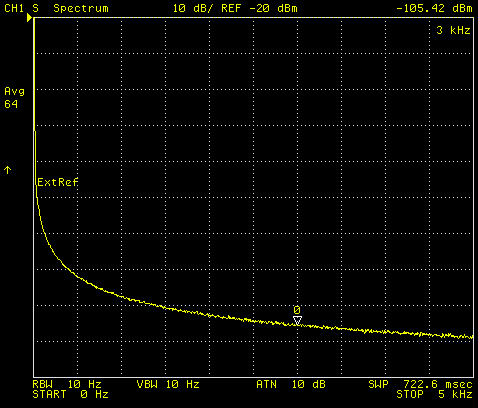 HP3325B adjustment 5-10: nothing to see :/ 5-11 and 5-12 Oscillator frequencyThis is another simple setting that requires minimal equipment. In my case it is a little useless because the 3325B is connected to my 10MHz house standard, as god intended. So as long as the oscillator is not completely off it won't have any impact. 5-13 Amplitude ModulatorAnother simple adjustment that use standard equipment. Basically we want to set the amplitude of a square wave to zero and it's DC offset to zero too. For this adjustment and the next one the 3325B is set on its side so you may need to tilt your head to read its display ;-) 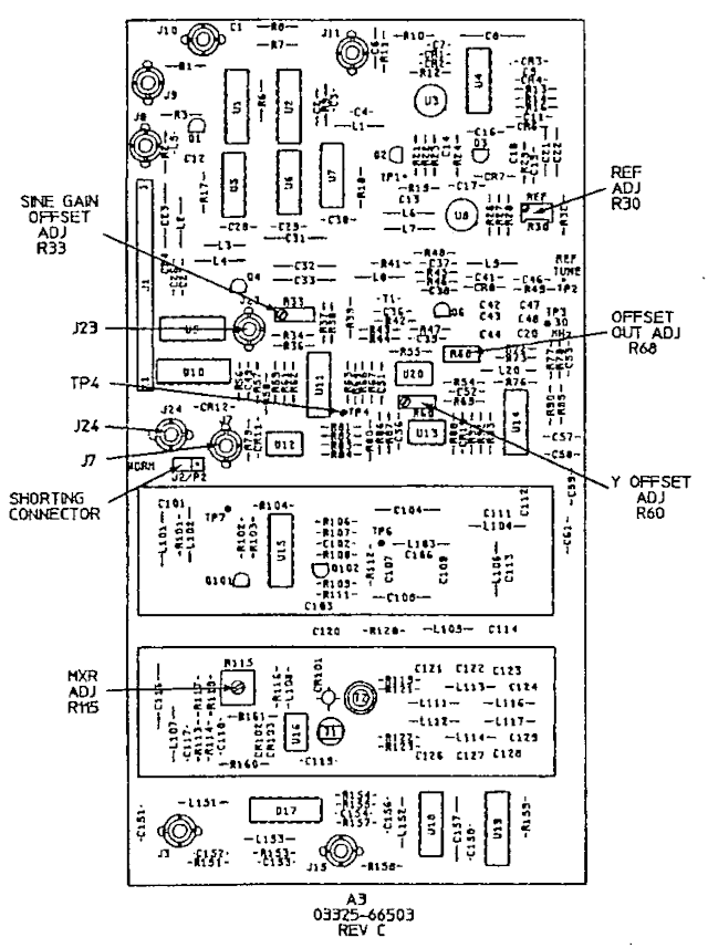 The A3 board adjustment locator  HP-3325B adjustment 5-13 amplitude is not zero 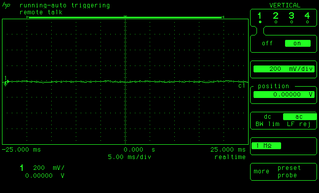 HP-3325B adjustment 5-13 amplitude is now zero  HP-3325B adjustment 5-13 offset is not zero 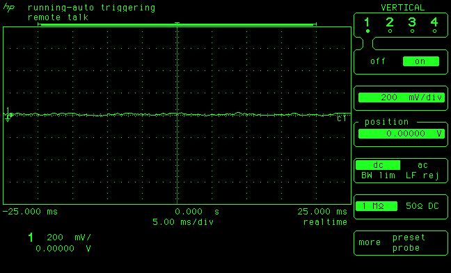 HP-3325B adjustment 5-13 offset is now zero 5-14 and 5-15 Sine/Square Wave Gain-OffsetThese ones are a little more original as one has to press the amplitude calibration button repeatedly between adjustments. But nothing complicated and best of all it requires no equipment at all! 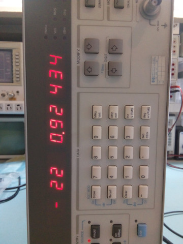 HP-3325B adjustment 5-14 -22 is too high, should be close to zero 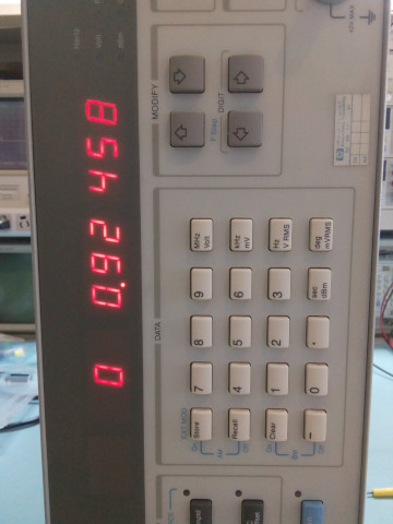 HP-3325B adjustment 5-14 is now at zero 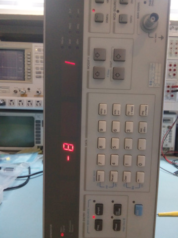 HP-3325B adjustment 5-14: final cal parameters should be within -60 - 60. Then we can also proceed with adjustment 5-15, which in my case didn't need any fiddling: it was good as is: 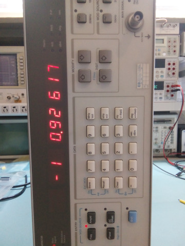 HP-3325B adjustment 5-15 already at zero 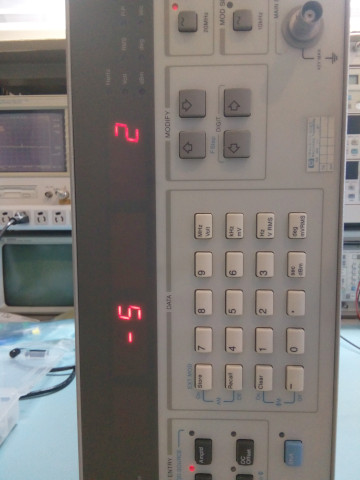 HP-3325B adjustment 5-15: final cal parameters should be within -60 - 60. 5-16 X-DriveI'm not sure of this adjustment is required for those who won't use the X-Drive output of the 3325B, which I suspect is 99.999% of the users. But hey, why skip an adjustment? I was surprised to see that it was quite out of specs for my instrument, probably because I skipped it last time I performed the adjustments. Since I don't work much with modulation it was also an opportunity to explore how the sweeps work on this machine. 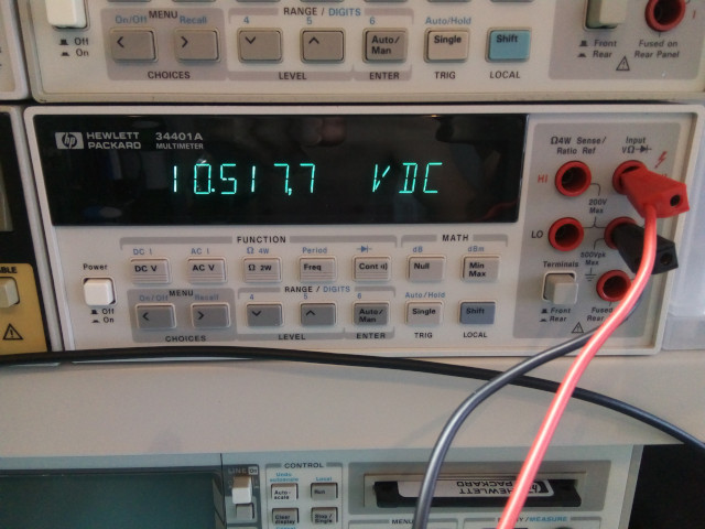 HP-3325B adjustment 5-16 value se to within 10.5V +/- 50mV 5-17 Amplifier BiasAnother opportunity to use the spectrum analyzer! Will it work this time? Yes, it does! Here's a couple of before/after pictures showing the little 20MHz harmonic being reduced 'a little'. Note that you have to pick the right hole in the shield: only one has an adjustment! Look in the whole and/or use the hole aligned with one edge of the U17 integrated circuit just below the shield 'can'. 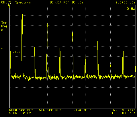 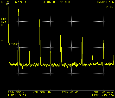 HP-3325B adjustment 5-17: before and after adjustment. Note the smaller odd harmonics. 5-18 Ramp StabilityThis setting was made a lot easier by using the "envelope" display option of my 54542A, something I've never actually used and discovered by chance while performing the adjustment. Noice. A big WARNING for this step: HP sets the generator at 10Vpp and then tells you to put that in the 50ohm input of your oscilloscope. The 54542A does have 50ohm switcheable inputs (yeah!) but is limited to 5Vrms when this low impedance is selected. Many devices have such "5Vrms" limit so it's a generic limitation and danger. 10Vpp is a little too close to the limit (10Vpp = 3.57Vrms) so I 1) reduced the amplitude to 5Vpp and 2) used an external 50ohm terminator instead of the internal 50ohm of the scope, for safety. Ths instructions for this step were also a little hard to understand, it was clearly written for analog scope in mind (ALT and CHOP are dead giveaways). Basically set the trigger properly and then use the delay control to move one period and use a small time base to observe the jitter. This must be repeated for 3 ramps settings. In my case all were within specs: 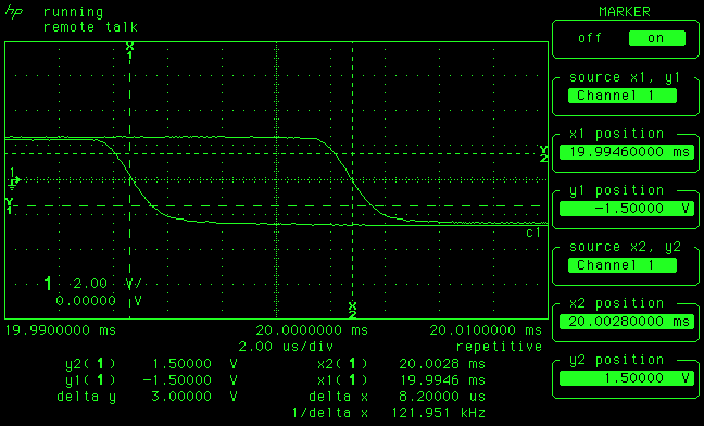 HP-3325B adjustment 5-18 (d): jitter is 8.2us 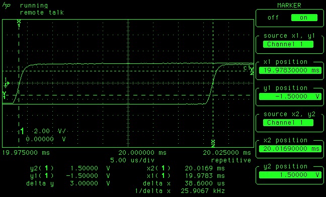 HP-3325B adjustment 5-18 (f): jitter is 38.6us, a little high but within spec 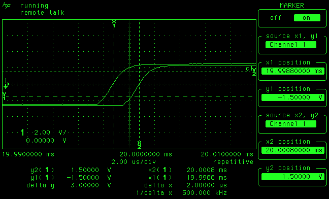 HP-3325B adjustment 5-18 (g): jitter is 2us 5-19 Amplitude flatnessI also had to skip this test as I don't have a "1Vrms 50ohm thermal converter". 5-20 Mixer Spurious SignalLast opportunity for the spectrum analyzer, and also last adjustment! We just need to minimize the mixer spur at 10MHz. Here's a before/after: 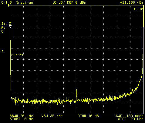 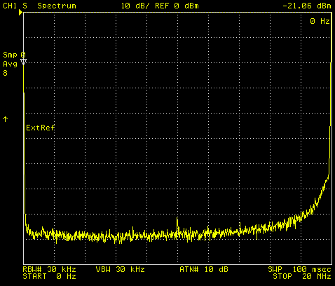 Mixer spur adjustment, before and after. The spur peak was already low, so only a minimal adjustment was necessary. Finally, as recommended in the service manual, here's a last screenshot showing the 2/3 harmonic at 12MHz (input 18MHz): 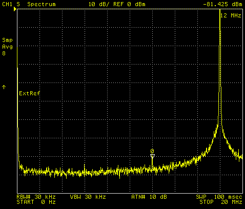 HP-3325B adjustment 5-18 (e): 2/3 harmonic check at 12MHz That's all folks! | |
| © 2024 Damien Douxchamps. All rights reserved. | |

