Hitachi V-525 analog oscilloscope maintenance | |
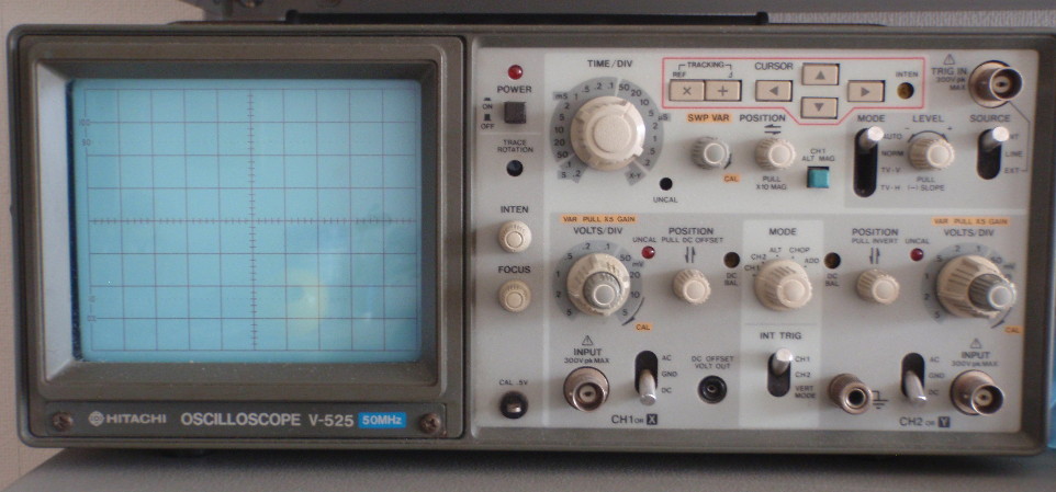 The Hitachi V-525 50MHz Oscilloscope Every electronics engineer should have an analog scope they say. Well I only got mine recently, after more than 30 years of soldering iron wielding. The Hitachi V-525 is an interesting little scope that belongs to that weird transition period during which scopes remained essentially analog but had some digital bits sprinkled here and there. For the V-525, this means an on-screen display of the timebase, the vertical scale (on channel 1 only) and the deltas (horizontal and vertical) between two cursors. Take a look at this beautiful display: 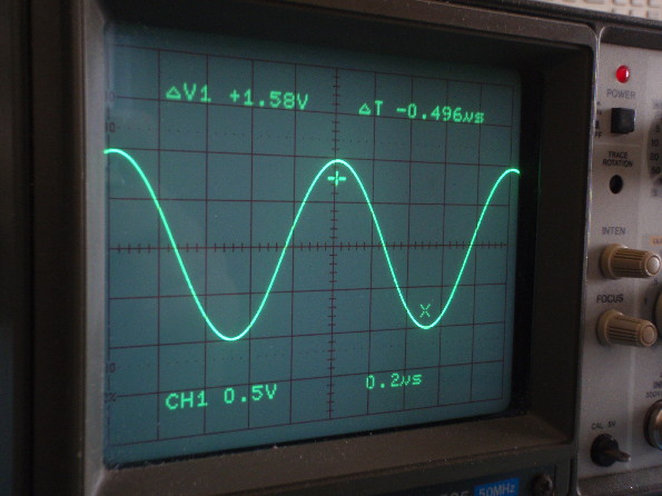 The Hitachi V-525 display. The bottom line shows the vertical scale on channel 1 as well as the time base. The top line shows the horizontal and vertical deltas between the two cursors ("+" and "x"). This scope came in very good condition and seems to have been loved by its previous owner, always a good sign. The only issue with it was a sticky vertical scale knob on channel 2 which also led to poor contacts for the V/div control on that channel. This is a common problem with old electronics that feature mechanical selectors: the grease gets old and starts to act more like tar than a lubricant, creating an unpleasant experience at best and a failure of the selector at worst. Let's open this baby up... 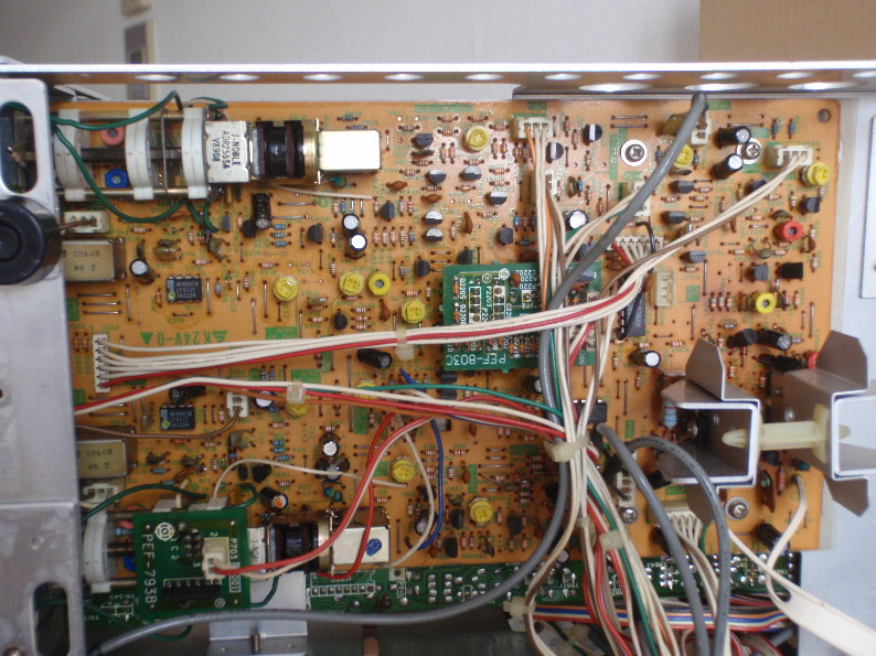 We're in like Flynn! The innards are typical for a scope of this era with mostly through-hole components and single PCB boards and, in typical late 80s fashion, some SMDs here and there. The large mechanical part in the upper-left corner is our vertical selector that needs cleaning. There's a similar one in the bottom left for channel 1 which has a little extra PCB on top to sense the position of the knob and later display the V/div on the screen. Note that these mechanical controls include a switch (pull x5 zoom), a potentiometer (continuous adjustment)and a selector (volts/div). The PCB must be extracted to access the selector/potentiometers which requires a bit of fiddling but is not too hard to do. It does take some time though: all the knobs have to be removed from the front panel, the screen bezel has to go and a few cables need to be disconnected. Once the 'control combo' is accessible we need to disassemble it to access the sticky shaft and poor contacts. The two long screws can easily be removed along with their spacers: don't lose those and remember which is going where, for they don't all have the same length... The little clip between the brass shaft and the cast (gray) base it's a bit of a pain to remove though, and it will also be a pain to insert back when we're done. 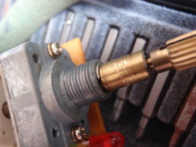 The vertical selector for channel 2, showing the little clip sandwiched between the bronze and cast parts as well as the two long screws' heads. Once that is all out of the way we can see the dirty and sticky grease on the bronze shaft, as well as the two little white rotary selectors that are on the shaft. The latter contain the dirty contacts that we have to clean: 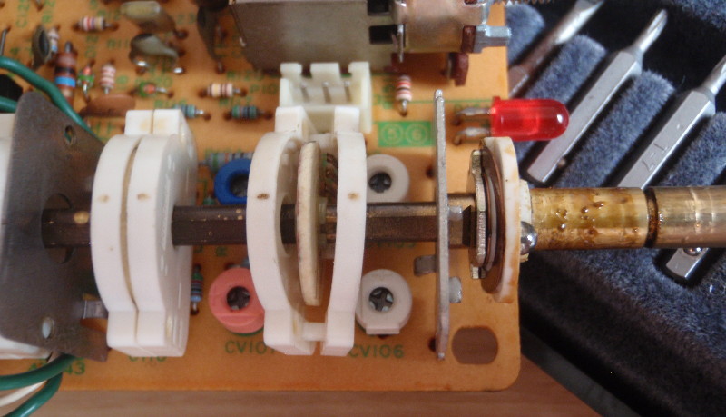 The dirty shaft and rotary encoders. Not wanting to desolder the entire channel 2 vertical control assembly I opted for gently separating the two halves of each rotary encoder and using a Q-tip with IPA to clean the contacts. There is barely enough space to insert the Q-tip but it does fit: 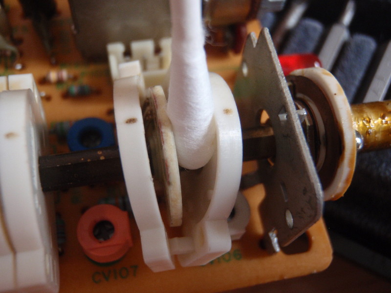 Cleaning the rotary encoders with Q-tip and IPA. Be very gentle with the Q-tip so as not to damage the white plastic shells. Cleaning the shaft itself is more straightforward: just remove the gunk, clean with IPA and add new grease. I only had silicone grease at hand, which is not ideal because it runs a bit too much, but it did the trick. All you have to do now is reassemble everything. After this little maintenance the scope feels a lot better and is ready for many more years of service. I may have to do the same for the channel 1 control at some point... | |
| © 2024 Damien Douxchamps. All rights reserved. | |

