Advantest R6144 voltage/current source stability issue repair | |||||||||||||||||||||||||||||||||||||||||||||||||||||||||||||||||||||||||||||||||||||||||||||||||||||||||||||||||||||||||||||||||||||||||||||||||||
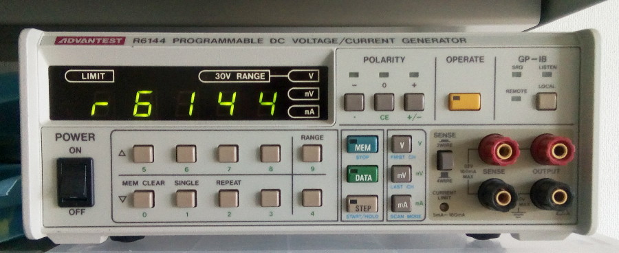 The Advantest R6144 programmable DC voltage/current source It's probably a good idea to check any instrument that you get from auction, but sometimes it can take a little bit extra and unexpected effort to get the gear into tip-top shape. When I received my Advantest R6144 source everything seemed very very good, with excellent accuracy measured with my 34401A. I ran a python script for 10 minutes on each range to check accuracy and drift on all voltage ranges and the results were good except for the 160mV range which is more than a bit off. And you know that you're going to discover something great when your reaction to seeing new data is "Hmmm, that's odd..." In fact the script was not really needed: the drift was apparent after a few seconds already! That one single range be of poor quality is actually not surprising for this type of instrument used in an industrial setting: the instrument has zillions of features but only a single setup will ever be used on the production line. So it seems this source was used exclusively in its 160mV range (or at least very often switched to that range), and was discarded and sold at auction after its performance became unsatisfactory. Not a bad score for a device built 20 years ago! Obviously we're going to try to extend that life a little bit further. I did notice that while other ranges were stable even from a cold start, the 160mV of the R6144 would veer off course quite fast and for a long time, never stabilizing on anything. Summoning the powers of Python (again!), I made a script to measure the output stability for each range. Each test had a cold start so I could see what stabilization should look like and what levels of early variations were acceptable before the source settled after reaching its operating temperature. The results were rather clear and confirmed the previous findings: the 160mV range had 'a bit of' an issue. See the graph below, where all ranges have been normalized to 160mV for comparison. The test ran for 10 hours (36000 seconds) for each range. 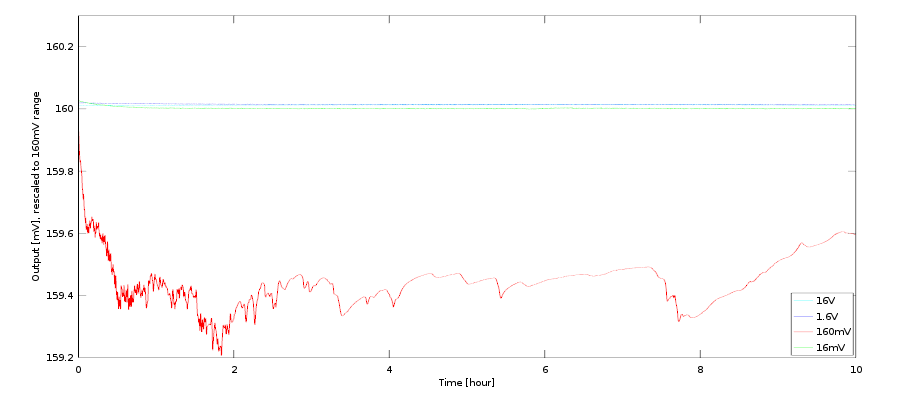 Advantest R6144 output stability in voltage mode. That red curve doesn't look too good... This is not a good spot to be in, because stability can be a real bitch to track down and fix. In this case the drift was not constant, but going all over the place. Vibration was unlikely and there wasn't even a device with a running fan in the rack at the time. The number one interesting bit was that only the 160mV range was affected. This meant that the reference inside the R6144 was still working fine (if there was only one, itself very very likely) but that some circuitry related to the 160mV range had an issue. Time to open that puppy and see what's inside... 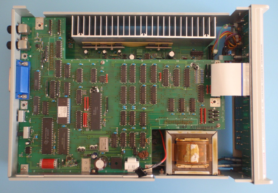 Upon opening the R6144 you are greeted by its digital board. The R6144 innards consist of two boards: a digital board on top with two connectors linking it to the bottom analog board. Communication between analog and digital boards is done through isolation transformers so as to completely isolate grounds and power rails. Classic for this type of equipment, although more recent ones would probably use optocouplers of even optic fibers (close inspection of the board revealed one optocoupler in this instrument too, for relaying info from the analog to the digital board). Removing a few screws (including two lateral ones for the PSU regulators' heat sink) reveals the bottom board in all its glory... and simplicity. That's a good sign! Pretty much all date codes are '00xx' so the device was assembled in the 2000's, but interestingly the dates on the PCBs are all 1991-1992. This Advantest model design is thus much older than the present incarnation. Another interesting thing: the analog board has all its components on one side (no SMDs here) except a larger trimmer which is mounted on the back. There is ample space on the top side so putting it on the bottom side (which would then require an extra soldering step) must have been done for a reason. My guess is that there will be less thermal variation on the bottom of the board, closely sandwiched between the PCB and the instrument's case and that's why they put it there. Still a little odd, but precision instruments often look like black magic! :) 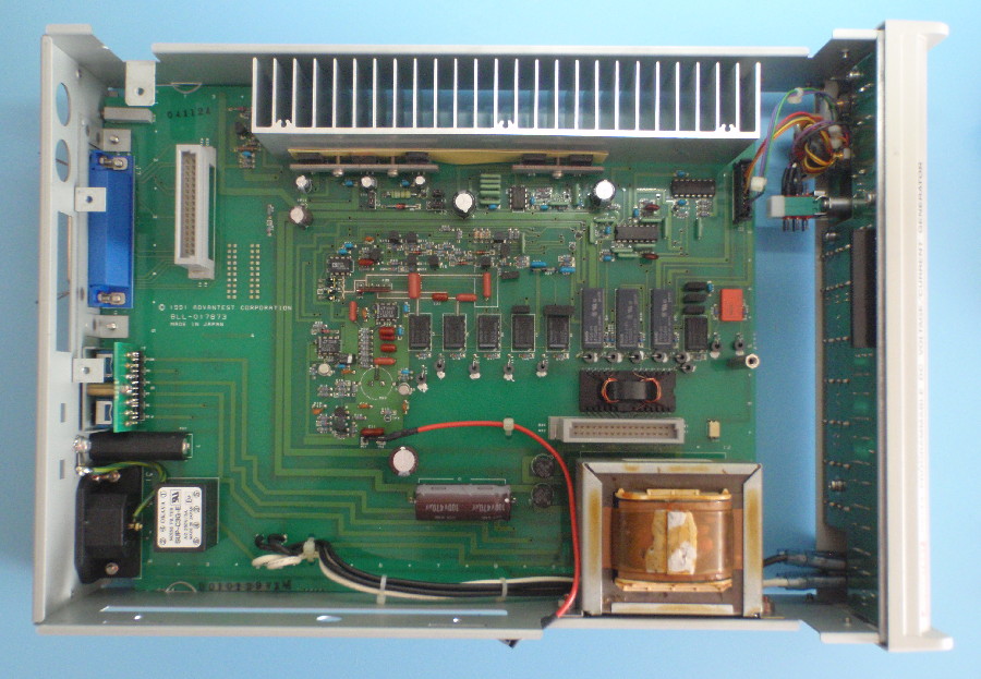 After a slightly cumbersome removal of the digital board we can have a look at the analog board below. The first good thing is that no obvious sign of damage is visible, which was expected given most things still work perfectly fine. Playing with the various settings I can hear relays clicking happily. Nothing obvious, which is not a great thing after all! After some unsuccessful digging here and there it's obvious a more methodical approach is needed. First one needs to identify what Signal Path (TM!) is used by that 160mV range, and given the number of relays it could become a bit hairy. Nevertheless this is an important step so let's get on with it. After probing the different modes of the instrument the following table can be drawn for the relays operation, where an X marks an active relay:
The great news is that only one relay is activated for the 160mV range, and that relay is also only active for the 160mV range. Thus, this relay defines that range (IFF for logic buffs), and something must be wrong around it. Now it's time to reverse engineer the output stage (since that's where the relay is located) and thus give a spin to Dave CAD (tm), though being a bit cheap I'll have to use Eagle instead. After a little untangling of traces this is the schematic I came up with: 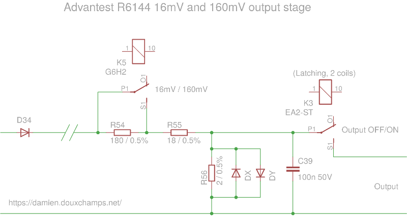 The 16mV and 160mV output stage of the Advantest R6144 Essentially the 160mV range is exactly the same as the 16mV range except for a relay that short-circuits R54, changing the output resistive divider from 1/100 (for the 16mV range) to 1/10 for our 160mV range. The remaining components are passives and a couple of protection diodes which I doubt very much would be a problem. Now R54 is also not a problem since the 16mV range uses it and works fine. Thus the only suspicious piece that remains is the relay itself. A faulty relay? Affecting stability? Surely you must be joking Mr. Feymann... Well it's easy enough to check: just put the device in the 160mV range first, then while power is on and still in that mode short the relay contact pins (be sure your soldering iron is isolated!). It's important to process in this order, otherwise your bodge may do some damage if it's not consistent with the source settings. The little bridge looks like this: 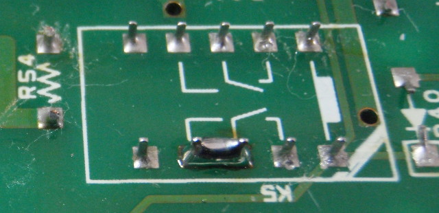 Shorting the relay in its '160mv' range position in the most brutal and simple way to remove the relay's effect on the output. If this results in a clean output then the relay is the issue. Otherwise... Argh. But sure enough, no argh this time: the output is perfectly stable in the graph below (purple curve, near the top). Note that the voltage is higher than before, and higher than the 160mV spec itself, because the short has of course removed the resistance from the relay contacts themselves. This all makes sense: being always used/switched to the 160mV mode, the relay contacts wore off a little, increasing their resistance, leading to a lower output voltage. This justifies the fact the drift was always lower than the expected value. What's more, if the relay contact is bad then small fluctuations in contact pressure could lead to the instabilities we're seeing. Promising! But not having a replacement relay I've tried a few more things in the meantime ('meantime which ended up lasting 3 weeks, see below...) 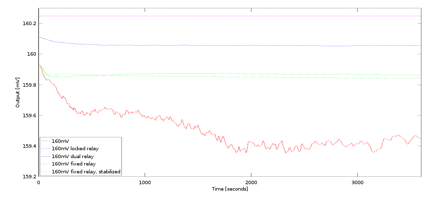 Advantest R6144 output stability on short one-hour tests and using various K5 relay hacks. Only half of relay K5 is used: the second switch is not connected. If, and that's a big if, that contact is cleaner and less worn out, simply using it instead of the current one could do the trick without replacing any part. The simplest next test is thus to use it in parallel with the current bad contact, using two bodge wires to connect it: 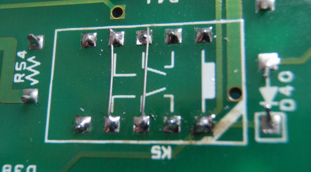 Using the two channels of the K5 relay just requires a couple of bodge wires... After an hour of data collection we have the new blue curve in the graph above. Voltage is now lower than the solder joint we made before (makes sense) but still higher than the target value since we are now having two relay channels (and thus resistors) in parallel. We can still see the drop at the beginning as well as small variations, which is also normal since the bad relay channel is still connected in parallel. But the variation is much weaker, which suggests that the contact of the new relay channel being used is much better than the 'worn out' relay channel. Now for the tricky part: remove the bad relay channel from the equation. This requires desoldering the relay, cutting some of its pins off, putting it back in and putting our bodge wires again. This is a bit fastidious but avoids changes to the PCB (like cutting traces) which I am a bit reluctant to do on a precision instrument. If you want to try this, don't push the relay back all the way in: leave a little space between the relay and the PCB to avoid accidental electrical connection of the bad channel. After yet another hour-long test the results are in and... well, it's getting there (green continuous curve): we still have an 'early' large variation due to warm up but it's more reasonable. Critically though, there are no more endless variations and the output stabilizes nicely after 20 minutes. A second test run right after the first one (green dashed curve) confirms that the first variation was due to normal warmup (no more initial variation). At this point it's clear that the relay K5 is kaput and needs to be changed: even the 'unused' channel has issues, which again is logical since it too has been switching when the worn channel was switching. Thus they have the same wear except for the effect of electricity which likely brought more damage to the used channel, maybe slowly eroding the silver plating of the contacts? Bad news there: this Omron relay G6H-2 is not manufactured anymore, and has no equivalent in the Omron range. Can't blame them too much: everyone is gone SMD now. Good news: Panasonic has an equivalent TQ2-5V that matches perfectly and is in stock at Digikey. And when I say perfectly I mean the most important figure, the contact resistance, is exactly the same and so is the coil current (down to the last decimal!). Clearly Panasonic had Omron users in mind there :-) Weather conditions in the US being what they were in February 2021 I had to wait 3 weeks to get that little relay. But once it arrived it was installed within a few minutes and a cold start test started. After a few hours the stability results are in and... it's a bingo! Check the beautiful new black line in the graph below: 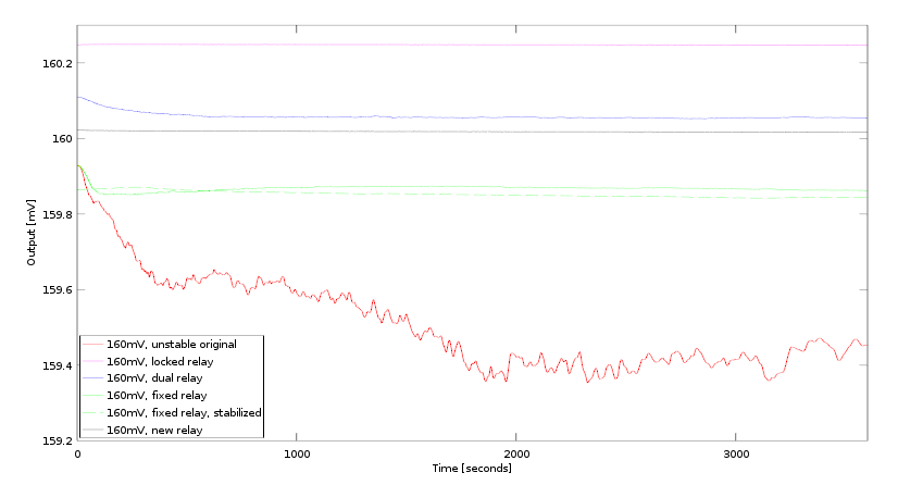 After the new relay is installed the results are back to purrrfect! Now that all ranges are stable we can have a look at how each one behaves during the first few hours of a cold start. The graph below shows the relative error in ppm for all 4 ranges. Well, 4/5 ranges, for the 32V range has been missing in this entire discussion! The red 160mV curve is now very good and it's the 16mV result that is not as good as it could. But it is actually normal: a cold start will affect a low-voltage range more and the extra noise is also expected, both due to the extreme limits of the R6144 source being tested and also because, well, the 34401 multimeter is not a 3458... Note the error is positive for all ranges, probably showing that the aging of the reference affects all outputs in the same direction. This is not important yet as I plan to recalibrate each range. 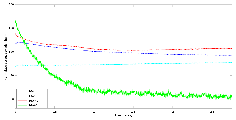 Normalized error [ppm] After an extra week of profiling we get the following graph showing 24h stability for all the voltage ranges: 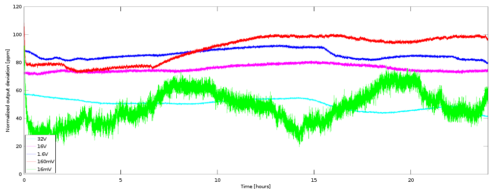 24-hour stability of the voltage ranges The deviations in absolute value are hovering around the +/- 50-100ppm mark. The corresponding calculated stabilities are:
The mean touches the different subject of calibration, and as we have seen above is still pretty much spot on with only a +/-1 on the last digit of the instrument. The stability is more than 10x better than the specs, except for the 160mV range where it is a little below 10x better. The larger variations are due to the room not being temperature controlled (total temperature swing of about 6 degrees), and mask the smaller constant-temperature drift so that the drift results are to be taken with a large bucket of salt. Several variations are also correlated to my activities in the room, like the drop in the 32V data near the end of the test, which corresponds to me coming back home after a hike. It seems like the sweat had a clear impact on the R6144 :-) The next step is to perform stability tests on the current ranges (160mA, 16mA and 1.6mA). A similar python script was used in conjunction with Octave for the graphs and after a few days we obtain the following results: 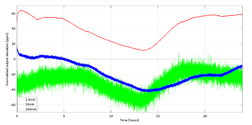 24-hour stability of the current ranges The current stability curves all show a clear dependency on the daily temperature cycle in my lab but remain within specs. Note that the large variations make it hard to assess the stability; one would need a temperature controlled room to get proper numbers here. The higher noise for the 1.6mA range also shows that the limits of my 34401A have been reached in terms of current measurement. Finally we can switch to the last step: calibrating the r6144. | |||||||||||||||||||||||||||||||||||||||||||||||||||||||||||||||||||||||||||||||||||||||||||||||||||||||||||||||||||||||||||||||||||||||||||||||||||
| © 2024 Damien Douxchamps. All rights reserved. | |||||||||||||||||||||||||||||||||||||||||||||||||||||||||||||||||||||||||||||||||||||||||||||||||||||||||||||||||||||||||||||||||||||||||||||||||||

