NI GPIB-120A bus expander/isolator | |
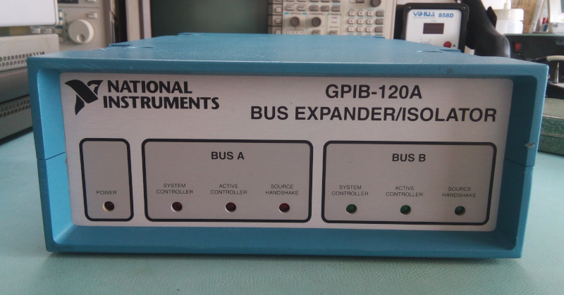 NI GPIB-120A front panel: just a few LEDs 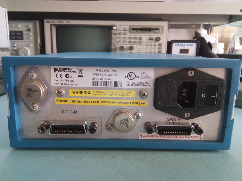 NI GPIB-120A rear panel panel: two 5V regulators, 2 GPIB connectors and one line input. Simple. When you start to have a lot of GPIB instruments you sooner or later find yourself buying and extra interface card or one of those goodies: a GPIB expander/isolator. These devices have never been very common and commanded a relatively high price of around $1000 in 2009, AFAIK. It's unsurprising few are lying around ready to be picked by hobbyists, and when they do the auction price can be crazy high, over $2000. So when I saw this one for under $50 I had to give it a try: first it seemed in great cosmetic condition and second it was sold with two 4m GPIB cables, and those can be resold for $15 a piece. So in the end this device may only cost me $20. Noice. But will it chooch? First a little thing regarding the rear panel: the device can be setup for wither 240V or 120V operation. That's great news because I've seen reports of single-voltage units that can't be converted. Good surprise! Next it's time to open this baby up, as we will of course take it apart before turning it on. Magic smoke, fried chicken, etc... 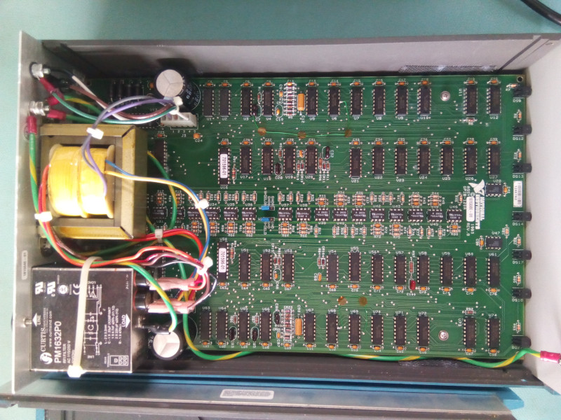 The main and unique board. After removing 4 little screws on the side of the case the top of the case comes off. First interesting design decision: the case is comprised of two identical L-shaped halves. Lower production costs, me likes. The case inner side is also covered with a ferrite-like coating and has metallic grills on the small ventilation ports. Not bad! 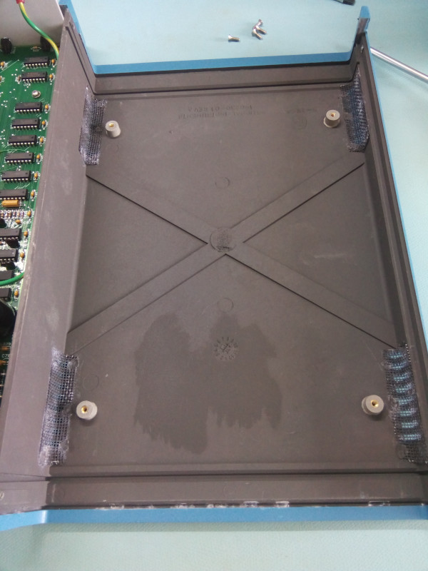 Inner side of the top clamshell with dark ferrite-like coating for EMC. The board itself is full 80s style with 100% DIP/through-hole and 0% SMD. The first obvious characteristic of the board is its row of optocouplers that cuts it in half: 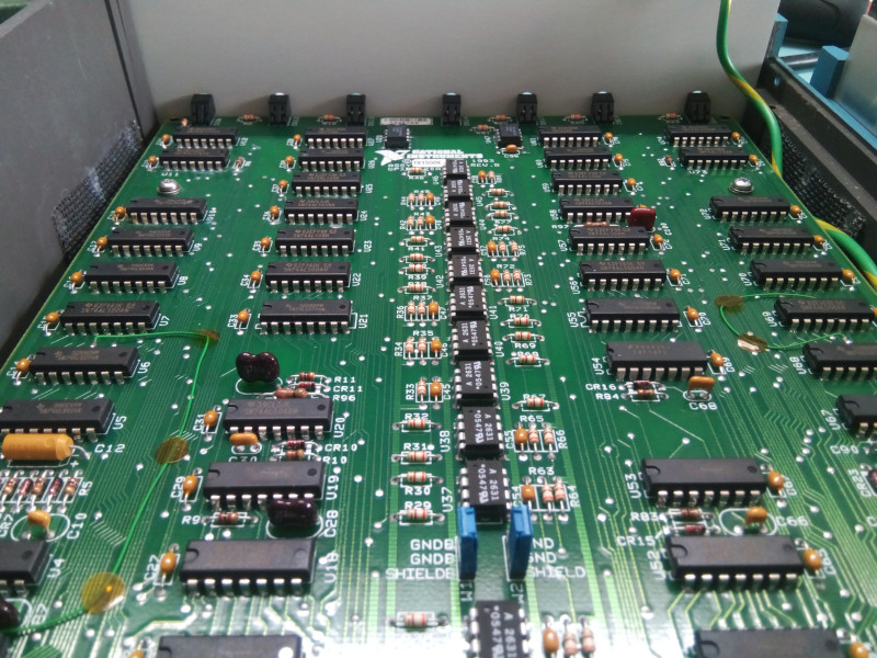 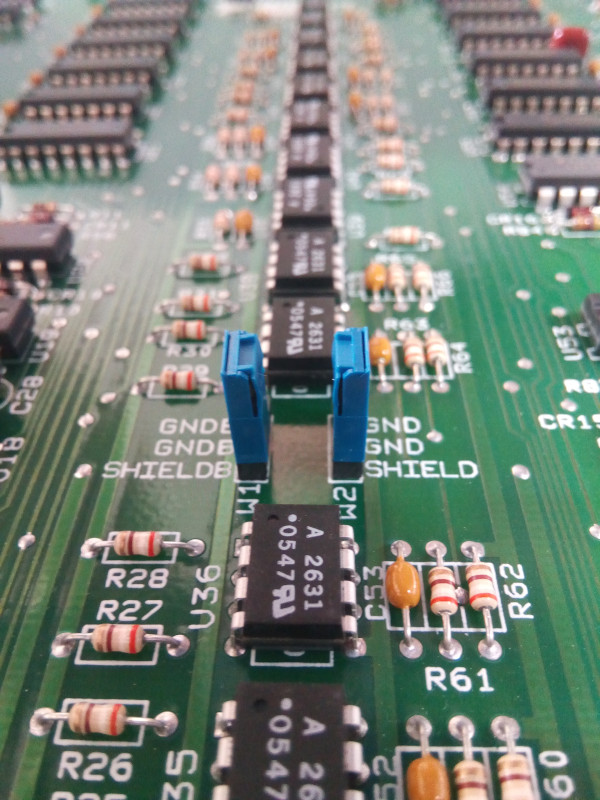 The optocoupler lines clearly separates both halves of the board While I plan to only use this device as an extender, it is also very clearly an isolator. The two halves are neatly separated by the row of optocouplers. And if both halves need to be isolated, then we will also need two separated power supplies and two separated transformer windings. Which we do have: 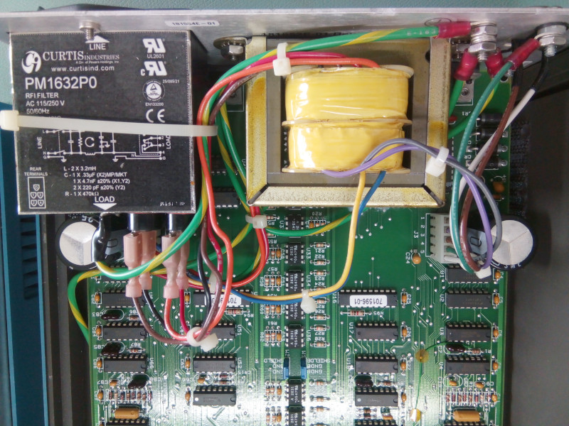 Dual PSU from two separated windings of the transformer. Note the two large filtering caps, one for each side of the PCB. 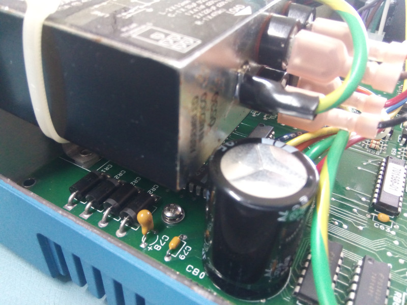 The supply circuit on the left of the board, complete with bridge rectifier 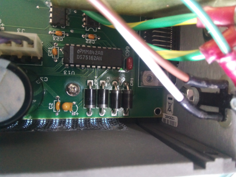 Identical supply circuit on the right. 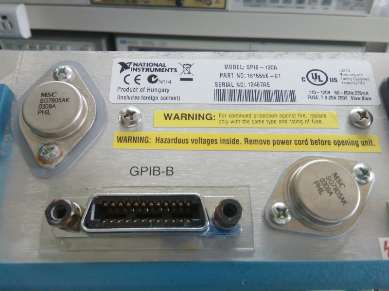 Two power circuits also means two linear regulators in full TO-3 glory The larger electrolytics are Nippon Chemicon branded, and we of course expected nothing less from National Instruments: 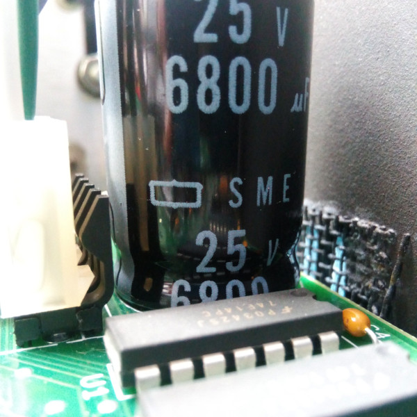 Good electrolytic caps! Staying at the power level we can see two nice grounding points, on on the rear panel and one on the front panel. The one on the front likely uses an insert and is compltely invisible on the other side of the front panel 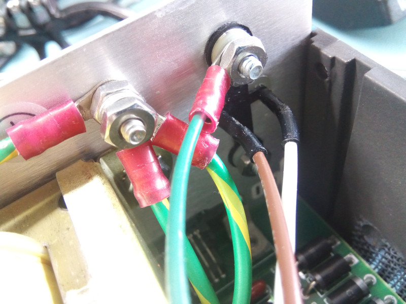 Rear grounding point 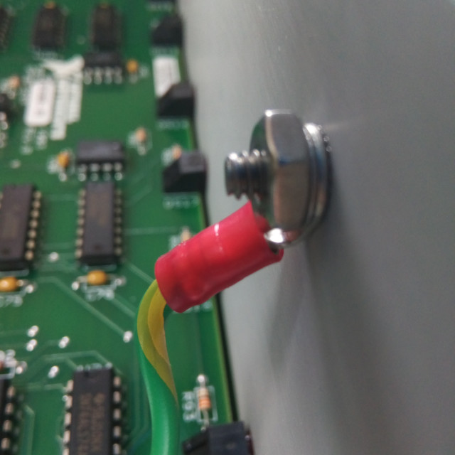 Front grounding point Let's now check the board itself. It is made entirely of discrete logic except for a PLD chip. I do spot a couple of evil tantalum caps, the exact same format as ones that I had to replace in my HP-3325B. There's also a bodge wire, one per side of course, which is stuck to the board by very small kapton pastilles. Many of which are not stuck to the board anymore. Boo. 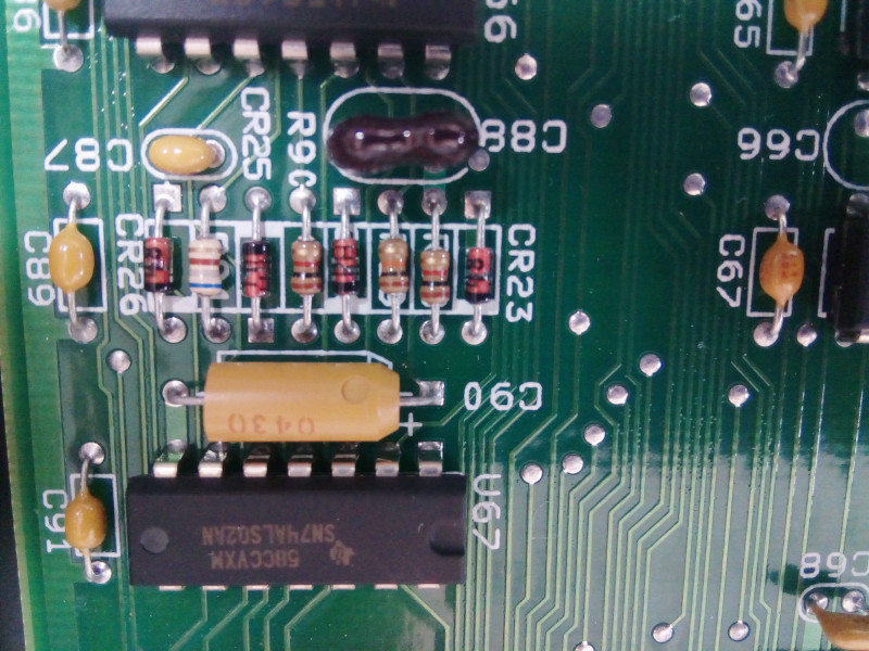 Evil tantalum caps, I have no fond memories of those... 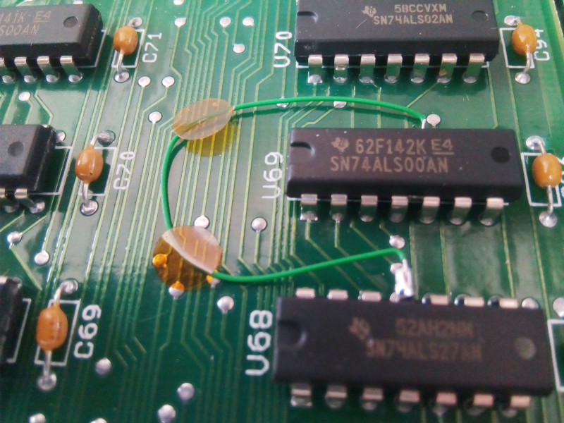 Bodge wire detected! Apart from that there's not much to say on this board. Clean, simple (?), still works after 20 years. Great work NI! Oh wait, we haven't tested it yet... Well no surprise here, everything works. A word of caution though: with PyVisa at least (but probably on all modern GPIB backends), trying to get a list of devices on the bus will not work anymore: the GPIB-120A will "report" that all devices are present. To detect the actual presence I forced an access on the device (for example, "*IDN?") during initialization. This will cause an error that can be caught with a 'try...except' in Python, thereby detecting the actual device presence. Other than that little difference, me happy :-) 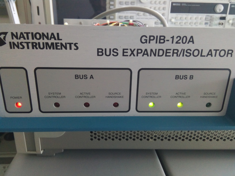
| |
| © 2024 Damien Douxchamps. All rights reserved. | |

