Tiny pH-meter | ||||||||
 This tiny pH-meter is very tiny: 11cm2 including the PSU circuit! I built it for the College Saint Pierre a few years ago. It is based on a circuit developped at the Facultes Notre-Dame de la Paix, Namur, Belgium. I modified several components to allow a smaller power supply (+/-5V instead of +/-12V) which could be used to power the display unit. I also spent 'some time' fitting everything on a very small PCB, just for the fun of it (and also because PCBs are sold per cm2 of surface). About 30 have been built and used for several years during college classes, demonstrating their reliability. Juste because it's damn small does not mean that you have to settle down for second best when it comes to performance. The repeatability is around 0.01 pH and the accuracy, while depending on how well you will calibrate it, is around 0.02 pH. The main characteristics are:
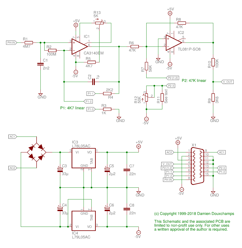
SchematicThe schematic is shown below. It is basically a simple gain/offset circuit with a high impedance input (several giga-Ohm) and frankly the explanation could stop here: anyone with an background in electronics can understand this. But I started to write a webpage about this, so let's try to do it right and describe the schematic.
The circuit input is pin 15 of X1. The probe signal enters IC1 via an RC circuit designed to allow only relatively slow signal variations (and avoid getting parasite HF signals). IC1 is a CMOS op-amp and thus has a very high impedance. The gain of IC1 is adjusted with the potentiometer P1. C2 is there for the amplifier stability. The R5/R13 circuit is the adjustment of the amplifier offset which is necessary for a high-precision application like this (see calibration below). Once the signal has been amplified it enters an offset circuit built around IC2. IC2 is a more classic TL081 op-amp commonly found in audio devices, among others. The offset is defined by resistors R12 and R7 as well as potentiometer P2. The first one is on the PCB and the second one on the front panel. This improvement on the original design (single pot) allows the range swept by P2 to be symmetric, albeit smaller than without R12. It can be skipped if you wish (those small SMD trimmers can be damn expensive...). The circuit is a classic op-amp "adder" and designed to provide an average offset of 2V. Indeed, first note that the input pin 2 of IC2 is a virtual ground (because pin 3 is grounded and, you know, op-amp stuff). The gain of each part mixed at the input will therefor be the bypass resistor R8 divided by the input resistor, all multiplied by -1 since we use the inverting input of the op-amp. That means Vout = -R8/R6 * Vin - R8/(R7+R12+P12) * -5V. R8=R6 so the gain for the pH signal from IC1 is simply -1. For the -5V input the gain varies from -47k/(56k+47k+50k)=-0.31 to -47k/(56K+50K)=-0.44 depending on P12 (from 0 to 47K). Hence the offset we add will be between 1.54 and 2.22 volts. But since R12 is adjustable this interval can be varied. Two possibilities exist:
These calculated values can replace the adjustable pot to reduce cost. In such case R11 can be used instead of R12. You could also decide to use a 40k resistor since it's a good middle ground that will simultaneously provide both a reasonable centering and a reasonable symmetry for the adjustement range. Note that both P1 and P2 are on the front panel, not on the PCB. As such they are not shown in the schematic; I have just inserted labels so you know how to connect them. After the offset circuit the signal passes through a voltage divider before reaching the display unit. The divider roughly changes the signal range to something that is acceptable for the display. The real setting will be done on the display itself which contains a multiturn trimmer to precisely adjust its input gain. If you use a display unit without such trimmer, you need to add this to your PCB. The voltage ranges for the signal evolve in the circuit as follows:
As you can see the electrode voltage is symmetric and must undergo a linear transformation to fit the 0-14 pH range. This is all very classic stuff... Note that even if the supply rails are at +/-5V the circuit can cope with a 0-4V signal because the output swing is almost equal to the rails (no 0.7V drop, more around 0.3V IIRC). A little remark concerning the integrated power supply circuit: it is a very small circuit that supplies a maximum of 50mA. Be careful of you want to add a power LED or something like that as it might be too much for the circuit. Check the total power used by the circuit before adding extras. PCBThe PCB is very small and you are advised to build it with through-hole mounting components if you're not familiar with SMDs (which also implies you'll have to start the PCB design from scratch). I personally think that it looks much cooler with a small footprint... No other special remarks concerning the PCB, except that the PCBs that were manufactured were slightly different (see the photos below). This is actually also true for the schematic. No functional difference, this is just a 2012 version versus the original one from the 90s. 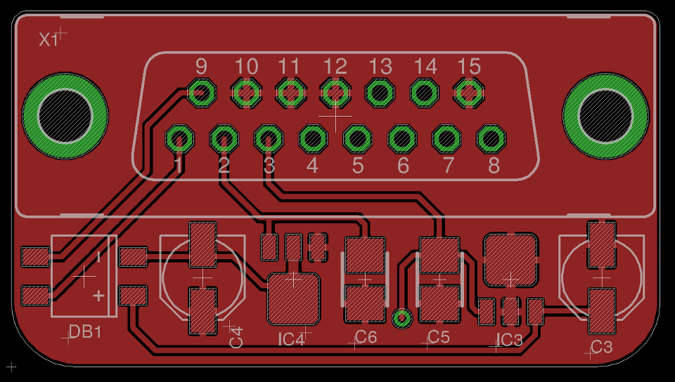 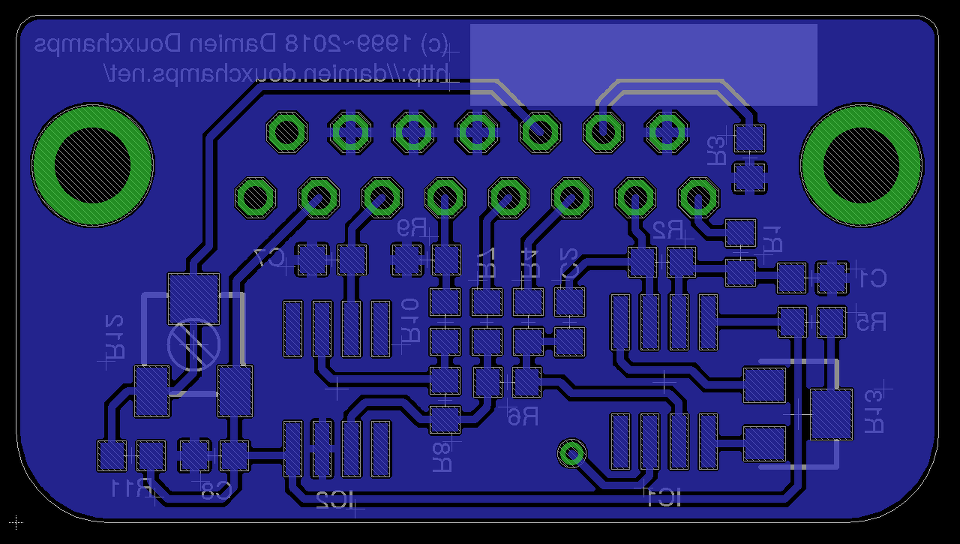 ComponentsThe components list can be infered from the schematic ;-) Remember to buy two potentiometers too; they're not in the schematic as they will be placed on the front panel. A little link to the display unit used in this project. I chose this one because it has a nice 'pH' unit that can be activated on the display. (I actually used the DPM 200, not the DPM 2000, but the "200" is not RoHS so it's not available any more. Use the DPM 2000 instead!) The pH electrode used in my school were the InLab 409 (IIRC) from Mettler-Toledo. ConstructionRandom remarks: start with the smallest components, go slow, don't forget to set all the solder bridges correctly on the display unit (what you want is a 0-200mV range, an appropriately set dot and 'pH' shown as the unit). Check your cables,... before powering up. The cabling diagram of the X1 connector is:
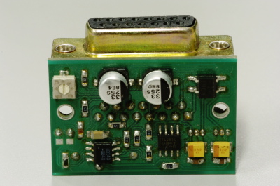
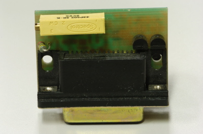
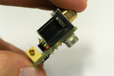
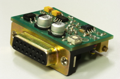
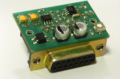
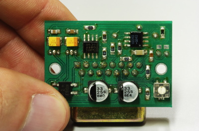
PhotosSome pictures of the first ph-meter built. The PCBs is from Eurocircuits: great value for money! I also recommend P-ban in Japan. Note that if you use a smaller connector the PCB could shrink a lot, but having a sturdy connector allows easy insertion and removal so I'm not sure if a smaller board would be much more useful in this case.
Circuit calibrationThe calibration procedure is not difficult but should be performed with precision instruments (IOW a $5 voltmeter might not be the best idea). There is only three trimmers to set: the multi-turn R13 for the offset voltage of IC1, the 'symmetry' trimmer R12 around IC2 and the trimmer on the display unit. We will set them in that order: R13, Rdisp and R12. The two other potentiometers are used for calibrating the pH meter before each use using known pH soltutions. Don't confuse these two calibration steps.... First set P1, R13 and R12 to their mid position and short circuit the circuit input. Measure the output of IC1 with a voltmeter and set it to zero volt with R13. Be as precise as possible! With the output still shorted, set P2 so that the output of IC2 is 2V. This setting might be difficult as ou don't have very accurate trimmers to do it. Don't worry: just set it around 2V and then do some math... The question is simple: what should be shown by the display for the voltage found after IC2? Since 2V is pH 7 the relation is pH=V*7/2. Given the voltage that you have after IC2 you can thus define what you want to see on the display. For example, if the voltage after IC2 is 2.053V the value that should be shown on the display is 7.186. Note that you can also choose an output value of 3-3.5V to obtain a greater display value and thus a greater accuracy in this setting. Anyway, you should now turn the trimmer on the back of the display unit until you reach the calculated pH value. And now you're almost done! Well, there's one more thing to adjust: the symmetry potentiometer. This can only be done by successive approximations but it does not really matter since this setting does not affect the final accuracy of the pH-meter, just its 'human interface'. The way to proceed is to look at the extreme values shown on the display when P2 is varied. If the average of these extreme values is very different from the one obtained when the potentiometer is in mid position you can play with R12 and see how it changes the variation interval of P2. After some time turning knobs you will have something nearly symmetric. UsageThe pH-meter must now be calibrated with known-pH solutions before it can be used. This should be done before each use. Imagine that you have a neutral pH solution (pH 7) and a alcali of pH 9. First put the pH probe in the pH 7 and adjust the offset (P2) to reach pH 7 on the display. The gain potentiometer (P1) should not have any effect on the reading since any gain applied to a zero voltage will yield a zero output after IC1 (remember that pH 7 correspond to a probe signal of 0V). If you see a (significant) variation it means that the pH of your solution is not exactly 7. More on this below. Note also that the response of the pH meter strongly depends on the probe and the calibration should be performed with stable values only. After calibrating the offset, put the probe in the pH 9 solution (gently wipe the probe to avoid contamination of the solutions, if your probe allows wiping). Don't touch the offset potentiometer P2 anymore, instead set the gain (P1) so that the display reads pH 9. The calibration is finished! If you have different known-pH solutions, put the probe in each of them to see if you get the right value. For example, since you used a 9 and 7 solution why not try an acid of 4? If everything goes well, you should read 4 on the display (I read 3.98). If you noticed a gain-variation with P1 during the offset calibration (done with P2) then you will have to repeat the calibration several times; it means that your pH-7 solution was not really pH 7. This iterative process can diverge if you're not close to the solution. In fact, you could actually use a pH 4 and pH 9 solution for the calibration, but this would obviously force an iterative calibration process and you usually don't want that. More detailsThe formula for the gain of the first (non inverting) amplifier is: G = ( RA + RB ) / RA where: RA = R3 + P1A and RB = R4 + P1B Since R3=1K, R4=2K2 and P1A + P1B=4K7, the gain of the above circuit is variable between: Gmax = ( 1K + 6K9 ) / 1K = 7.9 Gmin = ( 5K7 + 2K2 ) / 5K7 = 1.4 The amplitude at the output of the amplifier stage should be 2V. With a +/- 0.4V input, the output amplitude is between 0.56 and 3.16V, roughly centred on the desired 2V. If you are using a strange probe or if you want to measure something else than pH, the probe may output in a different voltage range, for instance +/- 0.8V instead of +/- 0.4V. In this case the amplifier stage will provide between 1.12 and 6.32V. Since this includes the 2V target, the circuit may work fine without modifications. However, if you want to have a better useful range you have to change some resistances. For instance, suppose that you want to be able to tune between 0.6V and 3.2V, just like it was the case with a +/- 0.4V input. This means that with a 0.8V input the gain should be between 1.3 and 4. Thus: Gmin = 1.3 = ( R3 + R4 + P1 ) / ( R3 + P1 ) Gmax = 4.0 = ( R3 + R4 + P1 ) / R3 3 unknowns, 2 equations, so we can fix one resistor, let's say P1=4K7 because potentiometers don't come in many different values. Then: ( R3 + R4 + 4K7 ) = 1.3 * ( R3 + 4K7 ) ( R3 + R4 + 4K7 ) = 4.0 * R3 Which immediately gives: R3 = 1.3 * 4K7 / 2.7 = 2K2 R4 = 0.3 * ( 1K5 + 4K7 ) = 1K8 These rounded values yield the following gain range: 1.26 ~ 3.95 So you just have to change R3 and R4 to 2K2 and 1K8, respectively. Since these values are close to each other you should take high accuracy resistors (e.g. 1%). They're not much more expensive these days. Modifying the shifter stage is left as exercise to the reader ;-) ConclusionsYou now have a tiny high-accuracy pH-meter that costs less than 100 euros. Given the price of the probes it's really negligible. Go ahead and build 20 for your classroom or lab! DownloadLicense: please read the license file provided in the archive below. It's really basic stuff: don't make money with this,... The Eagle project files are available here. The Eagle PCB/schematic editor can be downloaded for free on the Cadsoft website. Possible improvements on this design
| ||||||||
| © 2024 Damien Douxchamps. All rights reserved. | ||||||||