Always-on 10MHz reference mod for the HP53310A | |
|
The Hewlett-Packard 53310A modulation analyzer is an interesting beast, somewhat little known except among connoisseurs. It has an interesting high-stability time base option which uses the 10811-60111 quartz oscillator. 53310As are well aged by this point, which makes their high-stability time bases even more attractive as source for your 10MHz house standard (ovenized quartz oscillators get better with time like wine!) To keep the oscillator at the right temperature the HP-53310A's power supply is split in two: one normal part that powers the MDA when the back switch is flipped, and another auxilliary power supply (an APU in a racked instrument! Aircraft nerds rejoice!) that is always on, as long as the power cable is plugged of course. That APU provides 22V for the heater to keep the oven at the right temperature, ready to be used when the instrument is switched on. If you're not aware of it, without such offline temperature regulation it could take days for the oscillator to truly stabilize. But there is a little snag... You would think (at least I did) that the 10MHz REF-OUT BNC at the back of the instrument would give you that sweet 10MHz sine wave at all times, regardless of the instrument being switched on or not. But it doesn't. First there is no signal on the REF-OUT port at all when the device is switched off. Second, even when it's switched on the signal is more like a rounded square wave, not a clean sine. Why? The oscillator signal is piped through some of the device's logic boards, for example to perform phase lock with an external reference. When the main power is off, so are the main boards and thus no REF-OUT at all. All this is bad news if one wants to get a nice clean sine wave all the time. What do? The first thing to check is how all these parts are cabled together. The oscillator has two cables connected to it: a 6-pin connector and the output SMB coax. The 6-pin cable contains the 22V oven power lines, the rest of the oscillator's 12V power lines, one "oven good" signal and an unused pin. But before we delve into that let's open the back panel. I didn't completely remove it because that would mean disconnecting a lot of SMB, SMC and SMB lines deep in the device. Instead I pulled the rear panel ajar enough to be able to extract the oscillator. Yes, the oscillator is located on the rear panel, together with its special always-on power supply and transformer. Here's a view of the rear panel and the little space that is available to work if one doesn't remove all the rear panel BNCs: 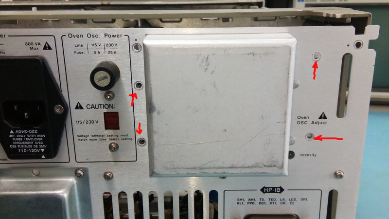 The back panel of the HP53310A with the oscillator assembly mounting screws marked. Remove at your own risk. Damien is a professional: don't try him at home! 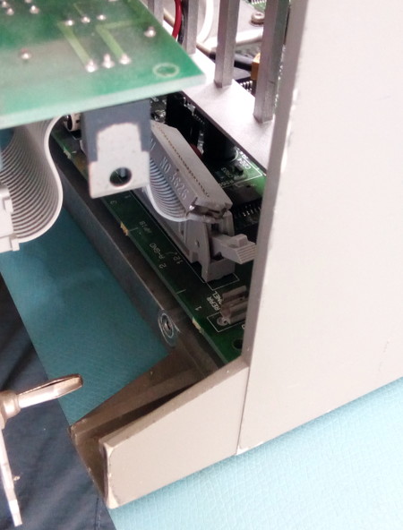 Little space is available when gently pulling the rear panel ajar. I recommend to disconnect the HPIB connector to make your life easier (don't forget to put it back in!). Also notice the holy ground pin, which also needs to be gently but firmly re-engaged when putting things back together. From there we can disconnect and extract the oscillator after remove its four mounting screws. The oscillator assembly consists of 3 parts: the 10811-60111 oscillator itself, its interface PCB and the mounting bracket. Plus two cables: the coax for the output and the power cable. 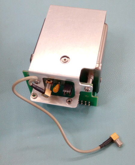 The 10811-60111 oscillator assembly. 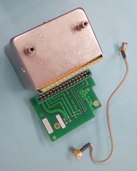 The oscillator, it's PCB mounting board and the SMB-SMB coax cable for its output. Before removing the oscillator it's worth testing it in-situ and confirm that it does produce an output signal at all times, even when the 53310's main power is off (remember that it runs on its own APU). Well well... What do we have here?? The oscillator does not produce any output when on the APU! Ooops. Now that's an issue... What could prevent it from generating an output? There is no control line and... ah. Yes. The 12V supply for the electronics is off when the main power is off. This complicates things quite a bit because now we have to figure out a way to generate 12V when the mains power is off! However, further examination of the APU circuit board (also on the rear panel) shows that it does produce 12V at all times. What is going on? Where is the oscillator supposed to get his 12V then? Let's have a look at that power cable. It's a bit more complicated than it should after all: it runs from the APU circuit board to the oscillator, but also has a branch that goes to the main board. Could it be the main board that switches the 12V? That would explain something. Let's look at the cabling diagram for this HP part (53310-60211-C is the reference for those playing along at home.) 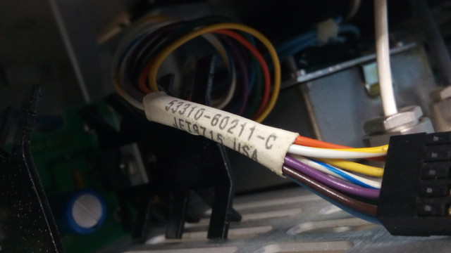 The oscillator power cable and it's official HP reference number. Good luck finding a spare part for this one. 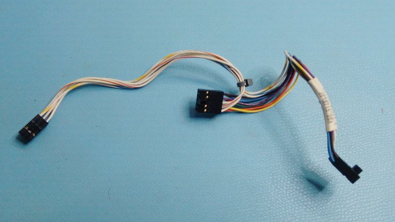 The complete power cable with its three terminals (left to right: oscillator board, APU board and main board connectors). 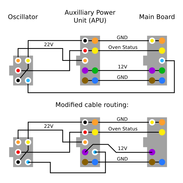 The cabling diagram for the HP63310A oscillator power cable 53310-60211-C and, at the bottom, the modification we're about to perform. The connectors are viewed from the 'solder side of the PCB they would be plugged into', in other words you're looking at the connector housing holes. The blue-white wire is the 12V for the oscillator, and indeed it comes from the main board instead of the PSU. The 12V from the PSU is fed to the main board through 2 lines, the green and purple wires (which are simply in parallel). So here's a genius idea (?): disconnect one of the 12V wires, for example the green one, then plug the blue-white that goes to the oscillator directly on the connector for the APU board! The 12V connections between the APU board and the main board is preserved thanks to the remaining purple wire and the blue/white wire can now feed 12V to the oscillator at all times. Even better: the wires are easy to remove from their connector housings so making the swap is simple and reversible. Noice. 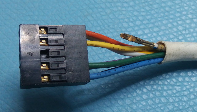 Cable being removed. You'll probably need to get rid of the heat-shrink HP label too. Does it work? Yes! The sine wave is now present at all times on the oscillator output. I don't think the reduction in the 12V cable cross-section (from two to a single cable) between the APU and the main board matters much as the oscillator is only supposed to draw about 40mA from the 12V and the main board probably doesn't draw another 2-3amps or so. Now that the 12V issue is solved we need to focus on exporting the sine wave out of the 53310. One solution is to use the REF-OUT cable and connect it directly on the oscillator's output. There's two problems with that. First the connector is SMB for the oscillator and SMC for the REF-OUT cable. Second, the main board doesn't like to not have its nice 10MHz internal signal, even if there is a input reference signal fed in the 53310A. So we need to somehow leave the circuit as is but pick the oscillator output and export it to a new port. This can be done with a circuit similar to what is found on distribution amplifiers: basically an op-amp that feeds an external port through a 50Ohm resistor (important for impedance matching). One extra little trick is that we only have a 12V power supply and an op-amp will require a symmetric PSU to get the job done given that the input sine wave is centered on zero volts. For that we can use input/output capacitors to decouple the op-amp from DC levels. We'll also need some extra resistors to create a DC offset of half the PSU to put the sine wave at a comfortable level at the input of the op-amp. Then a few PSU filter caps, a couple of resistors to control the gain of the operational amplifier and Bob's you're uncle! Here's the schematic I used, strongly inspired from a solution created by G4FRE: 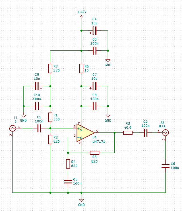 The schematic of my little oscillator output "distribution" amplifier. Strongly inspired by G4FRE. This circuit is quite simple but requires a good op-amp that is fast and has a high bandwidth. I used the LM7171, also used by the G4FRE circuit and one of the only good ones available on Digikey in a DIP-8 format. Because yes, I know that SMDs would be nicer (I've switched to 99% SMD almost 20 years ago) but in this case I'd like the project done fast and I don't want to wait for custom PCBs to get here. Interestingly, the PCB can be neatly sandwiched in the small space between the oscillator's body and PCB thanks to a 10mm+ clearance: 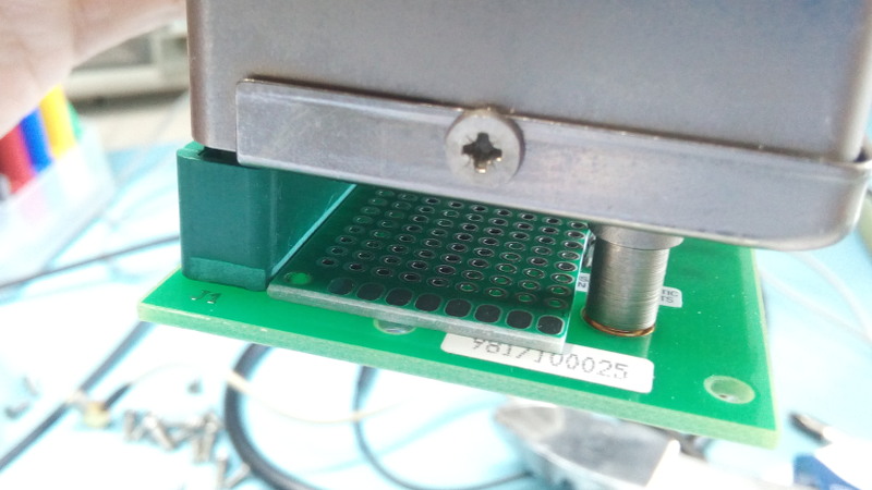 Clearance with PCB From there it's a "simple" but tedious matter of just hand-soldering and wiring the PCB, keeping in mind that there is very little height available on the 'solder' side which will contain all our SMDs. The PCB can be trimmed to a 9-pad width: 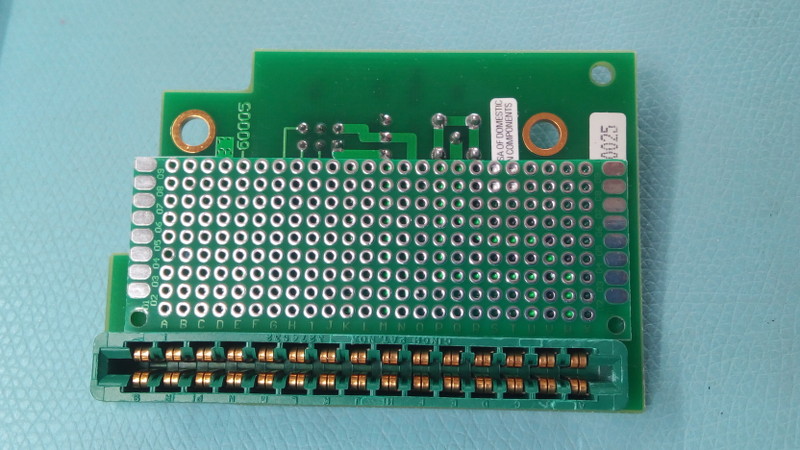 Our little 2.54mm-pitched PCB fitting nicely on the HP board. After assembly here's how the top and bottom sides look like. That won't win any soldering competition but I love the little retro steam-punk fly-wires look of it. Again, the SMDs on the solder side have to be very flush with the PCB to avoid excessive pressure on one component when we squeeze the board between the oscillator and its PCB (yeah I know lot's of talks about boards and PCBs here, sorry...) Here's how ti looks like: 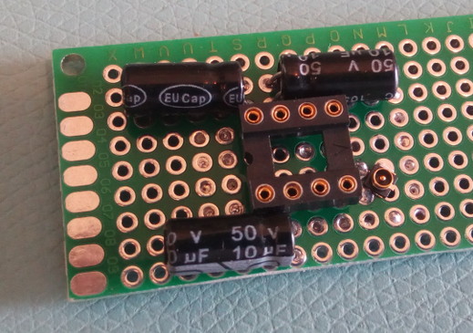 Oscillator output PCB, front 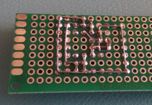 Oscillator output PCB, back We can confirm that everything falls into place, including the U.FL connector for the output. Those U.FL connectors are super tiny, but here's a top tip: you can use them on 0.1 inch pitch PCBs if you place them in the middle of a 4-pad square and tilt them 45 degrees! Note that the PCB was designed so that the input on pin 3 of the op-amp is aligned and very close to the oscillator's output on the HP board. In fact both ground and signal can be connected with very short wires. Important to avoid noise I think. After testing the circuit (and pulling what few hairs I have left on my head for 10 minutes because my scope decided to forget that my probes were x10) we are ready to attach it. There no hiding here, I have to show no shame for the whole interwebs: I used double-sided tape. Ouch. Of course there's an extra layer of 0.5 to 1mm or rubber to add compliance for the solder/SMD side. It's simple enough and works fine since there is a little pressure on the entire thing to hold everything together due to the limited height available in the space between the oscillator and the HP PCB. Double-sided tape, rubber, double-sided tape (optional) and the job's done! Then two wires for power and the signal input connection and we're done: 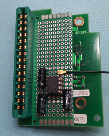 Last PCB check before mounting. 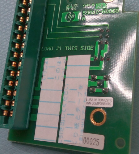 A little double-sided tape can go a long way... 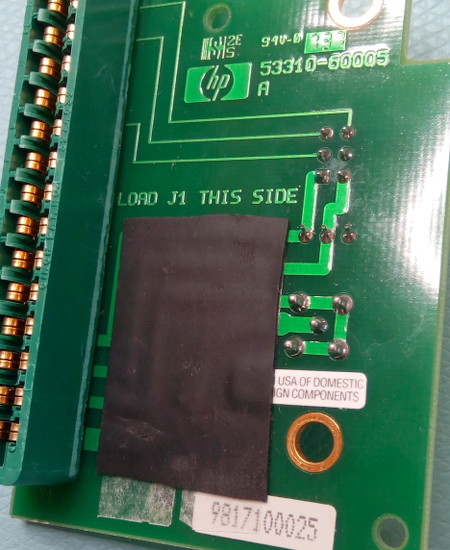 Adding extra rubber to fill the space and add compliance. After the oscillator assembly is put back together this is how the narrow space looks like: 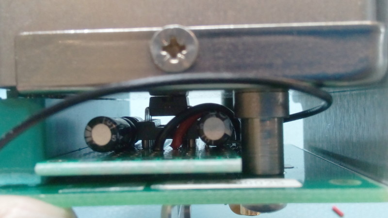 Not a lot of space, but just enough of it! Don't forget to re-insert the HPIB cable when putting everything back together. Once it's all over the rear panel should look like this, with the little SMA connector being the only visible change: 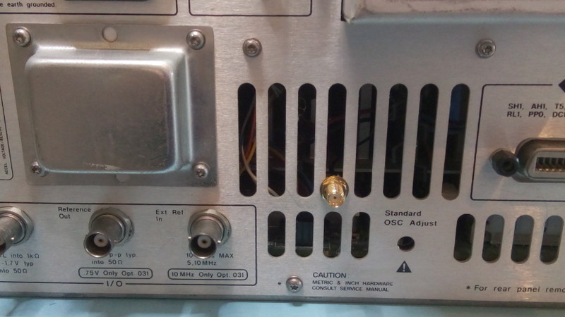 A thing of beauty and a joy forever. Ah but another important point. You may wonder why an SMA connector instead of a more common BNC. Two reasons. Firstly an SMA connector fits perfectly (really perfectly) in the ventilation slots in the back of the device. No need to drill and thus completely reversible! Secondly SMA-U.FL cables are cheap on Digikey. Few coax cable have that nice property. It is also another good reason to choose U.FL as the second connector in addition to fitting in the narrow space we had. The only catch is that you may need to buy an adaptor or a special cable to connect to your house reference distribution box. Of course while this pages details the procedure for the HP53310A you can probably easily adapt it to other HP instruments that use the 10811-60111 oscillator as well like many high-end counters and signal generators. The 53310A can also be a cheap way to get your hands on a nice, aged and cream-of-the-crop quartz reference that you can later integrate in other projects. Enjoy. Here's a little test as epilogue. The REF-OUT of the 53310 is now connected to my custom distribution amplifier which feeds the reference to a 53131A counter. The reference signal is also piped to the input of both the 53131A and the 533310A. Here's the result for the 53131A and 53310A: 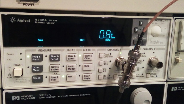 Checking the reference frequency with a 53131A whose ref-in is the reference itself too. The counter finds an error of 0.8uHz, or 8*10e-14. 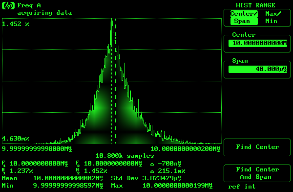 Checking the reference frequency with the HP-53310A itself. The error is -700nHz, or -7*10e-14. The two measures are practically identical even though the 53310a uses its internal path for the reference while the 53131a goes through the present mod and the distribution amplifier. Not a perfect measurement of how things are (I'm not a time nuts!) but it's good enough for the girls I go out with... | |
| © 2024 Damien Douxchamps. All rights reserved. | |

