Keisoku Giken EL-302RA electronic load | |
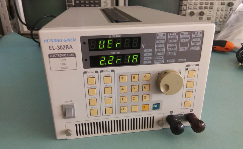 The Keisoku Giken EL-302RA, a little known but full-featured electronic load One piece of equipment that was still missing in my lab was an electronic load. And while I like HP gear they're not very specialized in loads. I had to cast a wider net to find a model that had all four modes CV, CC, CR and CP (constant voltage, current, resistance and power). The Texio/Kenwood models looked quite nice but every mode is an option (!!) which makes finding a fully loaded second hand model quite complicated. Plus they were only 150W. In the end the Keisoku Giken EL-302RA came out as the best: 300W, front terminals (not common on HP gear), all modes available, spec on par or better than HP and fitting in a rack. Although that last point turned out to not be completely true: while the EL-302RA has the proper width it is slightly higher at 148mm than the standard 3U height of 132mm. Oh well, all the other boxes are ticked including GPIB so let's not make a fuss... Time for an onboarding teardown! First a look at the rear panel: 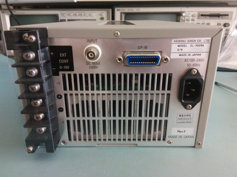 The back panel of the EL-302RA. Everything is nice and clean in the back too. Contrary to HP the serial number doesn't really tell us the manufacturing date so we'll have to dig a bit deeper to get that info. But one sticker shows an update to firmware version 2 which is nice (I suppose, no idea what the upgrade means...) Here I have to add that the nice people at Keisoku Giken were very helpful and kindly sent me a user manual without which the load would be a little bit useless. Kudos to them! Another important feature of the EL302RA is its 100-240V mains range compatibility, something mandatory for me or anyone who moves around a little in the world... While we're still on the outside note that the top handle is recessed in the body of the load, quite nice for racked systems. Another good reason to buy this model! There is also an air intake in the front; when opened it reveals a very very clean air filter. Good omen for the state of the innards. Speaking of which, let's get this puppy open. Three little screws and we're in: 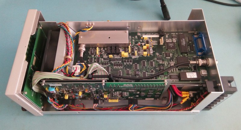 We're in like Flynn! As clean as a whistle indeed! The quality and cleanness of second hand gear in Japan never ceases to amaze me. Woot! As expected the load is built around a large heat sink and a 120mm front mounted fan. Large fan = good for noise so me happy. The three sides of the fan hold different boards: power supplies on one side, main board on top and analog circuits on the other side. 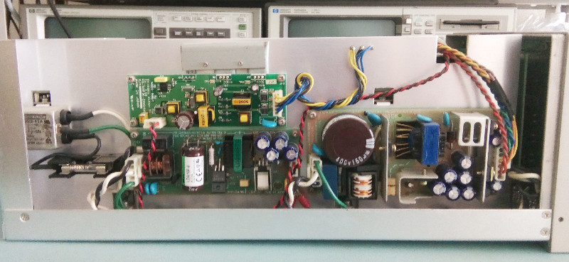 The PSU board The PSU side contains two OEM switching power supplies from Cosel. No surprise to see low power supplies here: although we're talking about a 300W load it's only here to sink the power provided by another supply and so we only have modest power requirements. A third board is made by Keisoku Giken and is likely a DC-DC converter. Its blue-yellow-black cables pass through nice little isolators, cool attention to details! 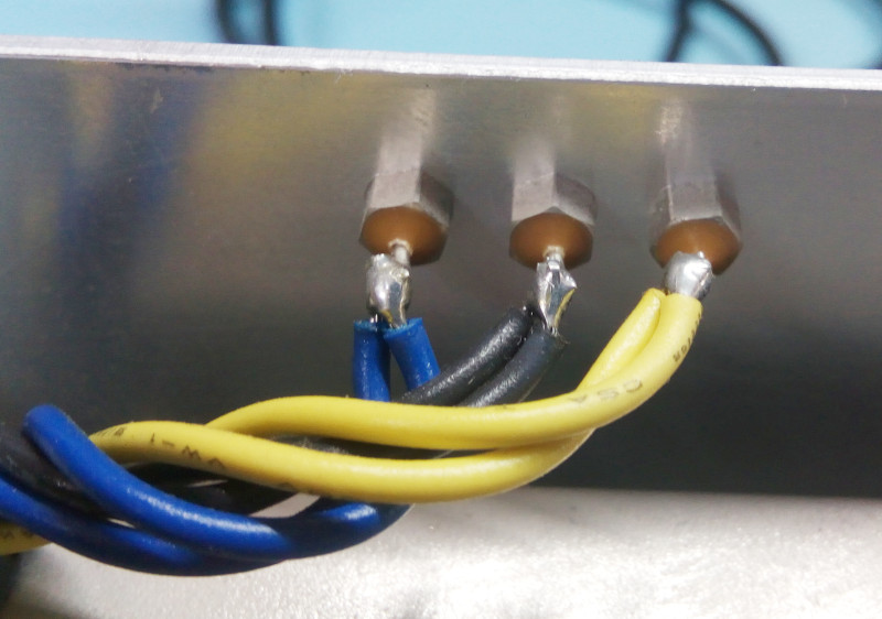 A good and well isolated pass-through However there's a sharp square opening to let other cables pass on the right, not so good. But no huge deal either. 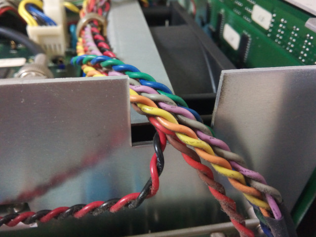 This pass-through could be better... 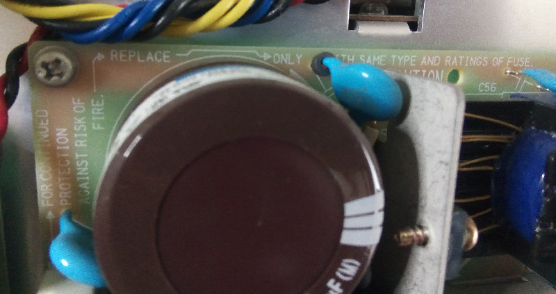 Funny warning split in different sections 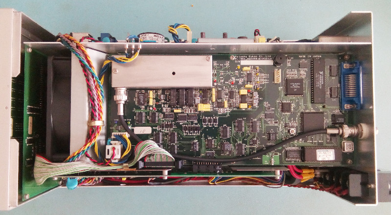 The main board The main board contains the GPIB interface, EPROM, CPU as well as the voltage measurement analog circuitry. The latter is cluttered around the RF can and its BNC cable. This load can do nice ripple measurements so special care was made to have clean small voltage sensing capabilities. Here's a view inside the 'can' which contains nice RF relays: 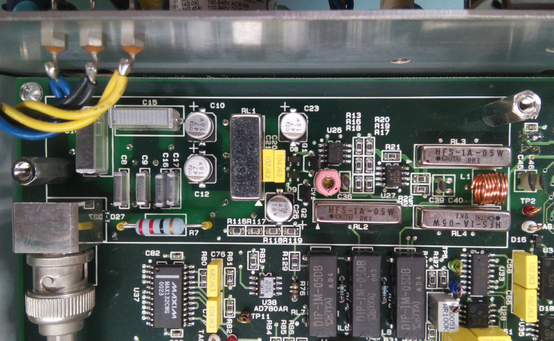 Inside the RF can On this picture you can also see the voltage ADC U37, a MAX132 from Maxim (18bit, serial output). Next to it its a precision voltage reference, an AD780. From the date codes on the ICs the load was built after the 20th week of 2001. Here's a view of the ROM sticker, which is a little bit more recent (2002?) and likely reflects the real manufacturing date: 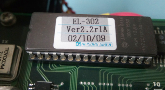 ROM sticker detail: release 2.2r1A from, I guess, October 9, 2002. 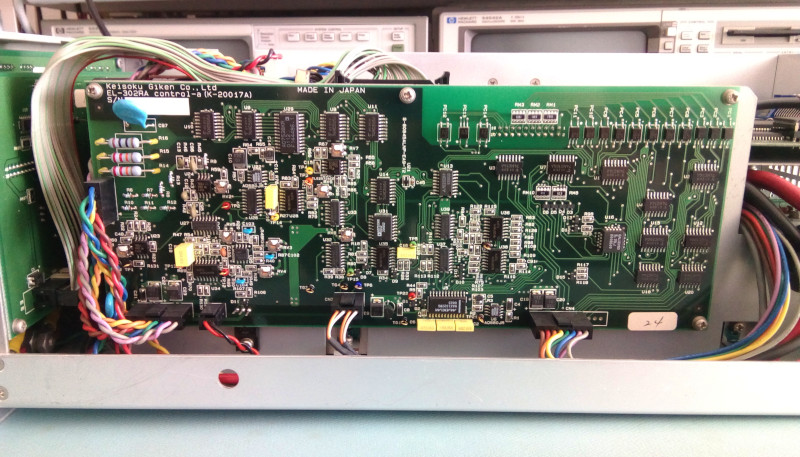 The analog/control board Finally the control board contains mostly analog bits and is linked to the main board through a lot of optocouplers. I'm not going to pretend I know the architecture of this load (or other loads for that matter) but my guess is that the optos are related to the transistors (FETs) that actually take the current load and are located on a deeper board, close to the heat sink. The board contains a 14-bit DAC (AD7538), a 10-bit DAC (AD7533) and, again, a MAX132 18-bit serial DAC for current measurements (U5, at the bottom near the row of 3 yellow caps) with its voltage reference (AD680, U6) and even its own negative rail regulator (79L05, Q1). It's also full of TL074/72, nothing wrong with a good op-amp. To access the front panel boards we must first remove 3 screws at the bottom of the front panel, then 2 screws on each side. Before unscrewing the PCBs the front knob must be removed by loosening two little hex screws (I used a miniature 1.5mm Allen wrench). Then the four screws attaching the PCB sandwich to the front panel can be removed and the PCBs extracted after detaching the flat cable. 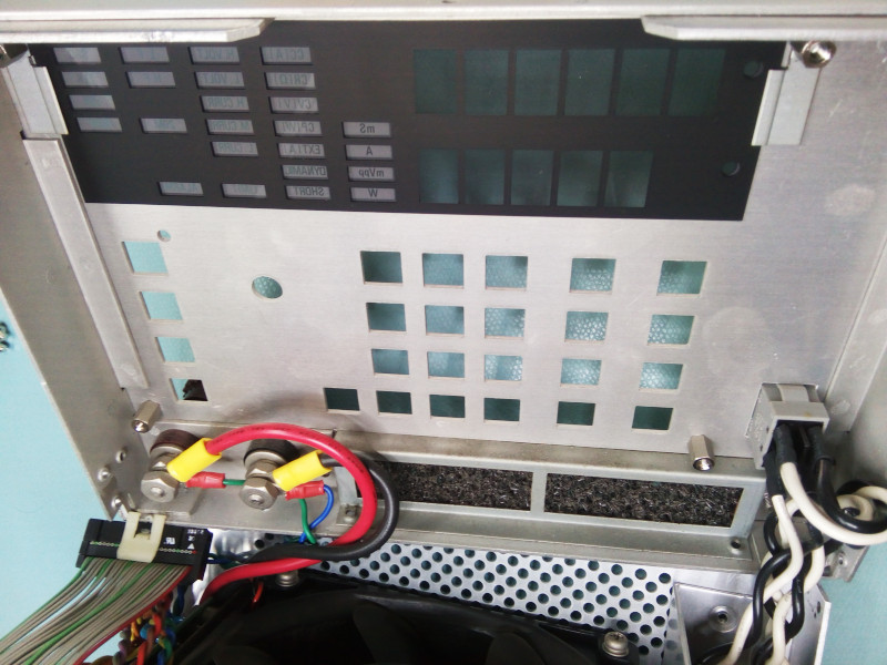 Front panel after removal of the PCBs 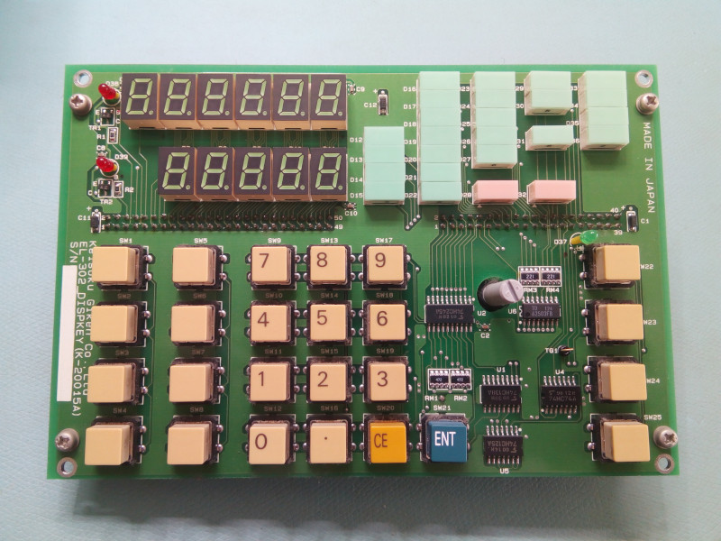 Front panel PCB sandwich Here's a couple of shots of the upper PCB with the rotary encoder. The encoder is from Bourns, and similar models can be found in HP gear too (like the 34970/34972 data loggers). And to finish off a close-up on those cute and a little old-fashioned LEDs for the load modes and settings: 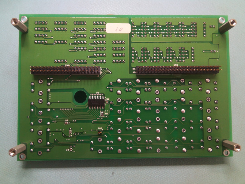 Top front panel PCB, side A 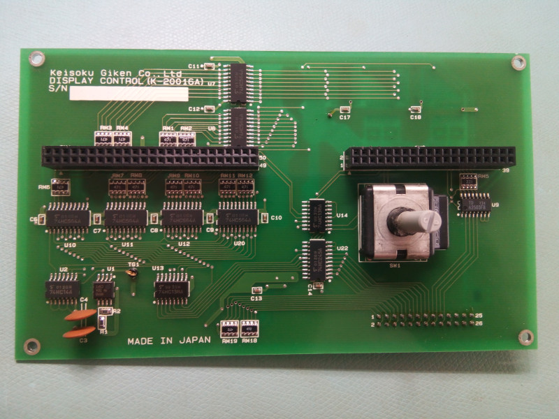 Top front panel PCB, side B 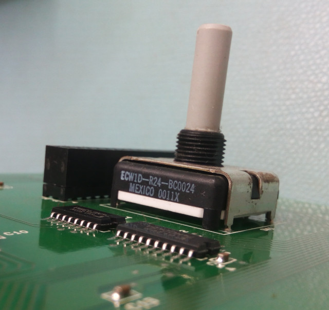 Optical encoder from Bourns, ref. ECW1D-R24-BC0024 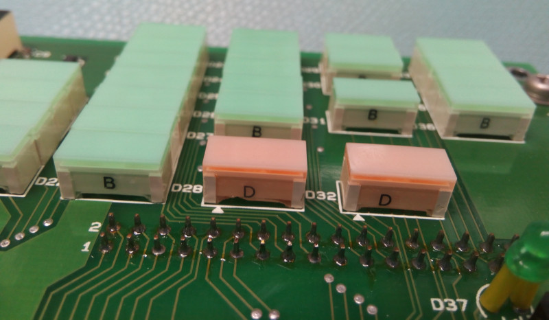 Cute LEDs Digging deeper into this load will lead us to the "big guns" board that should contain a collection of FETs and current-sensing resistors. But to get there we need to remove the top digital board, which also requires removing the 'analog' board on the side. Then a shiled/support must be removed to finally access the FET board. Note that the top digital board has one plastic mounting screw due to the proximity with the RF shield around the voltage sensing part. The spacer there is also plastic: don't overtorque those plastic bits! Here's the FET board: 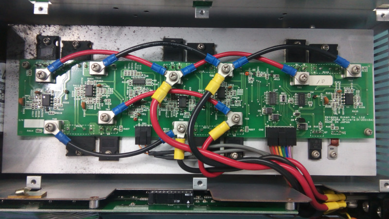 "Guns, lots of guns": big FETs and big current sensing resistors all mounted on the main heat sink. The circuit consists of five identical parts placed in parallel, each comprising an FET (IRFP250) and a large current sensing resistor, as expected. The resistors are from a brand I have never heard of, Isabellenhutte, model PBV 0.022 Ohm, 1%. Looks like a very specialized and cool company! Each FET+resistor pair has a sensing (and possibly driving op-amp), and the load measurements of the 5 channels seem to be compbined by U8 (another op-amp) and sent out via the CN1 connector. On the todo list: retrobrighting the keys that are a little faded and maybe replace the front terminals that don't accept banana jacks (like most other loads). Or maybe I'll just buy/make one of those banana adapters.. | |
| © 2024 Damien Douxchamps. All rights reserved. | |

