Aladin interfaces :: 4M7 problem | |
|
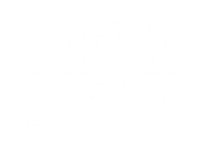
First idea: limiting input capacitance When I saw that resistor on the circuit for the first time, I thought there was some typo, but it was not a mistake. Pretty strange, for such uge resistors are seldom seen in op-amps circuits. And indeed, Matthias told me there was bugs, but it could be avoided in all cases with a 470k as replacement. Let's see the math behind this... First a general comment related to op-amps circuits: on should avoid using such over-Mohm resistors, for they can bring unstability and noise in the system unless a dynamic analysis of the schematic has been made. Moreover, the input DC impedance of the op-amp can be as low as 2M (e.g. uA 741), which means that a parasitic resistance is smaller than an 'interesting' one (4M7). This could lead to unacceptable errors in the overall circuit design. However, they use a 10M in the application examples you can find in the datasheet of the LM258/358. I assume it's OK then... Now, let us compute the hysteresis thresholds of this circuit. The interesting part is represented on the figure below.
The first threshold is computed when the output of the circuit is set to 8.5V (10V-1.5V, see the datasheets) (one of the two possible states of the op-amp, since it is in wired positive reaction). Let us write the basic equations of the currents at the input node:
i1 * R1 = V - Vh,
i3 * R3 = -Vo - Vh,
               Vh
i3 + i1 = i2 = --.
               R2
Merging this to find v yields:
     R2 * R3 * V + R1 * R2 * Vo
Vh = ----------------------------.
     R1 * R3 + R2 * R3 + R2 * R1
With a +/-10V supply (V=10V, Vo=-10V/+8.5V), we obtain Vh1 = 6.817V and Vh2 = 6.758. The hysteresis width is thus HW= 6.817 - 6.758 = 59 mV, which is nearly the value written on the original schematic. Actually, the 54mV of the original schematics are computed using a +/-8.5V output, but the datasheets refer to +8.5/-10V output... The problem is the current flowing through the 4M7 resitor. One can easily compute the current i3 to be 358nA when the output is positive, 3.56µA when it is negative. If one imagine a 100pF parasitic input capacitor (which is possible given the bad solders,...), the 54mV hysteresis change at the input can be done only at a certain maximum frequency, above of which the system can't catch up. This frequency is calculated using the charge/discharge equation for a capacitor:
    1
i * - = V * C,
    f
where i is the charge/discharge current, f is the maximum frequency, V is the voltage gain/drop (thus equal HW) and C the capacitor value. When the output is negative, the capacitor charges through the resistor R3, and the maximal frequency is 607kHz, well above the 19200Hz of the interface. When the output is positive, the current is only 358nA, and the maximal frequency drops to 60.7kHz, which is still well over the 19200Hz of the interface. The system can catch up in all cases, and transmission errors won't occur. We note that the capacitance required to make the system erratic is 316pF, a less probable value. However, since the chage/disccharge is not linear as approximated here, it is still possible that this would cause a problem. Since the limiting factor might still be the input capacitor, it could explain why a bad interface will never work. If an interface sometimes works, sometimes not, I would say we need a noise analysis, or maybe the capacitor changes significantly with temperature and humidity? Anyway, lowering the 4M7 to 470k will lead to 10 times more current, and 10 times the max frequencies. It can thus solve the problem, but the hysteresis will be around 10 times the original 59mV. Although is seems not to be a problem, one could stick to the original schematics hysteresis values by also lowering R2 and R1 by a factor 10. The current through R1 and R2 is then around 1.4mA, still a reasonable value. I would recommend that last solution, but I need to try it first.
Second idea: bad impedance match (thanks to Malin Dixon for the original idea and additional data about the Aladin) First, some additional informations about the Aladin analog properties.
From this, we can foresee some problems... Indeed, the 220k resistor will make the data pin voltage very high, nearly as high as the +10V supply, and make the voltage swing very small. This is due to the impedance of the Aladin, combined with the fact that there is around 8.5V (1.5V less than the power supply, see the LM258/358 datasheets) present at the output of the op-amp connected to the 220k resistor:
                            1M
Vpin at 0V from Aladin = --------- * 8.5V = 6.97V
                         220k + 1M
                             1M
Vpin at -3V from Aladin = --------- * (8.5V+3V) - 3V = 6.43V
                          220k + 1M
                            1M
Vpin at 3V from Aladin = --------- * (8.5V-3V) + 3V = 7.51V
                         220k + 1M
Compare these values with the thresholds of 6.82V and 6.76V. It is clear that 7.51V is well above the 6.82, but the 6.97V is above the 6.76! It is thus impossible to make a complete hysteresis cycle! The real problem is that the circuit is based on an unstable parameter of the op-amp (the max. output voltage), which not only changes from op-amp to op-amp with a variance greater than 54mV, but also changes with temperature,... The circuit is thus ill-conditionned, and is bound to work only 'sometimes'. Why is the replacement of the 4M7 with a 470k always working? The thresholds are in that case Vh1 = 6.864V and Vh2 = 6.292V, the hysteresis being 572mV. These calculations are thus not able to explain the fact that a 470k replacement is good. Anybody has an idea? | |
| © 2024 Damien Douxchamps. All rights reserved. | |

